
The Electrical control cabinet is now in construction, this cabinet houses both of the Solar Controllers, Generator control panel, Battery Meters & switching systems for the RV’s power requirements. (This unit does not however contain the Safety circuits for the 240v AC power supply, This is in a separate control box mounted above the Driving position.)
The Electrical control cabinet is being constructed immediately behind the driver against the Drivers side wall & over the Main power inverter, This is the point at which the Mains power can be connected to the RV.
The only 240v AC power systems in the Cabinet are the Selection / Isolator switch which allows the power supply to be switched from the Mains to Generator power or back again, which ever is not in use is isolated from the Power. The other 240v AC circuit in this unit is a 16 amp Residual current/Circuit breaker device which supplies a single Power point & can only be run from the Generator for using an ARC Welder if needed. Both the Circuit breaker & Selector switch are housed in a small mains circuit box in the lower front of the cabinet.
By placing this cabinet in this area of the RV it allows all of the electrical controls & metering of both the AC & DC systems to be monitored & adjusted easily as they can be observed from the Entrance of the RV & the dual purpose Passenger/Lounge & computer desk seat. The Battery selector switches are within easy reach of this cabinet allowing the Battery charging & usage to be controlled from the same point in the RV.
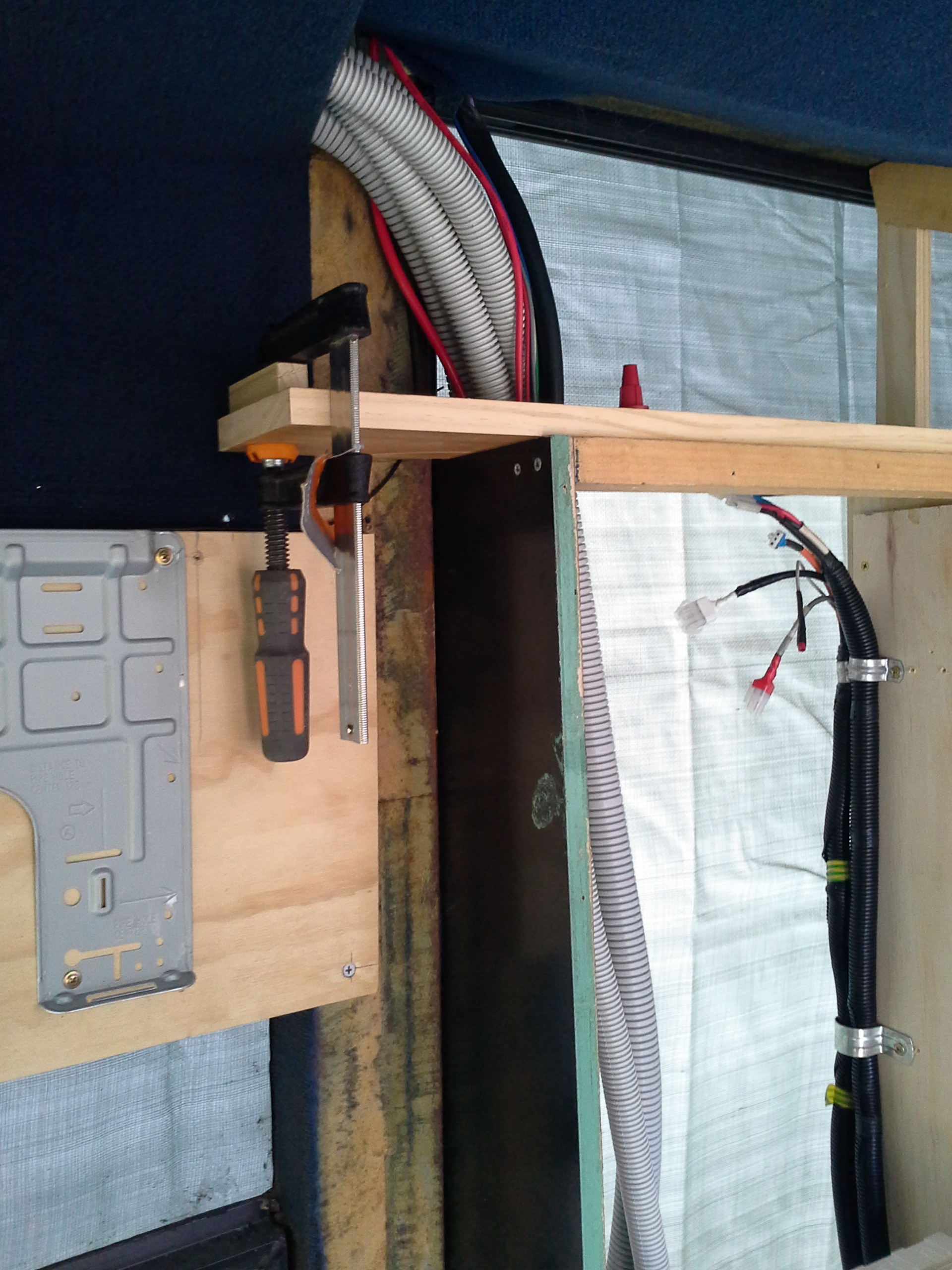
Start of the cabinet construction.
The Black conduits running up the R/H side are the remote control cabling for the Generator mounted in the Forward most R/Hand storage Bin.

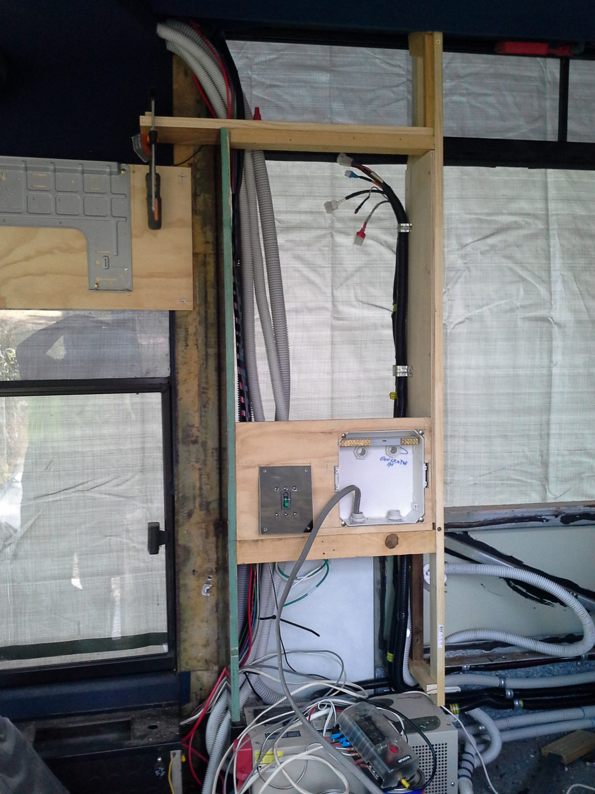
The Power box on the right will house the Selector switch to allow the power source to be chosen from the Mains or on-board generator, It also will contain a safety switch for the 15amp circuit for welding directly from the Generator.
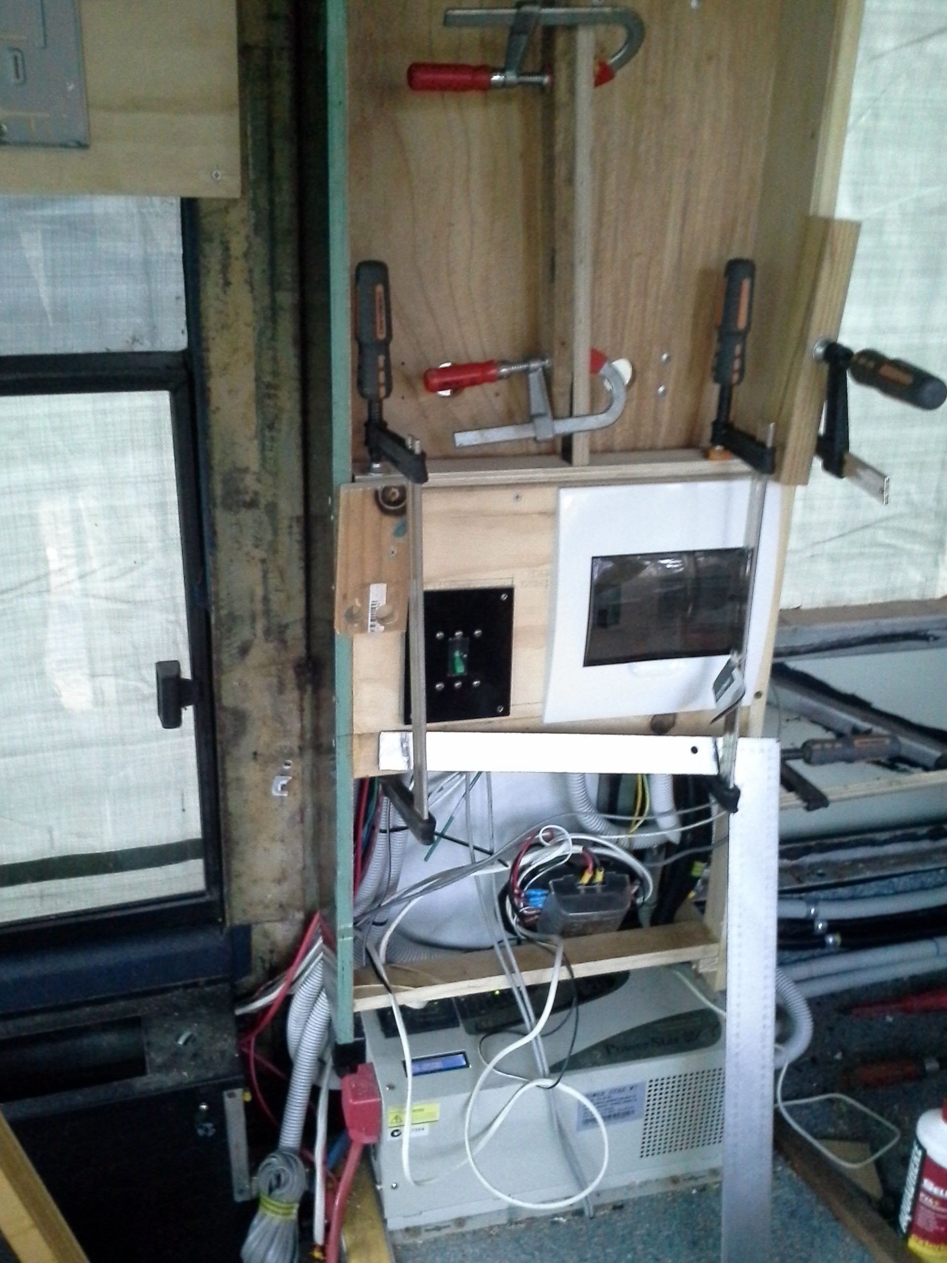
The large white unit below the Cabinet is the 7000w Inverter / Charger.

The Black switch panel to the left of the white switch box is a fault safety switch for the twin 80amp Solar controllers, A requirement when linking 2 Solar controllers to 1 charging circuit?

Both Circuit breaker safety switches are in the same panel on the Cabinet.
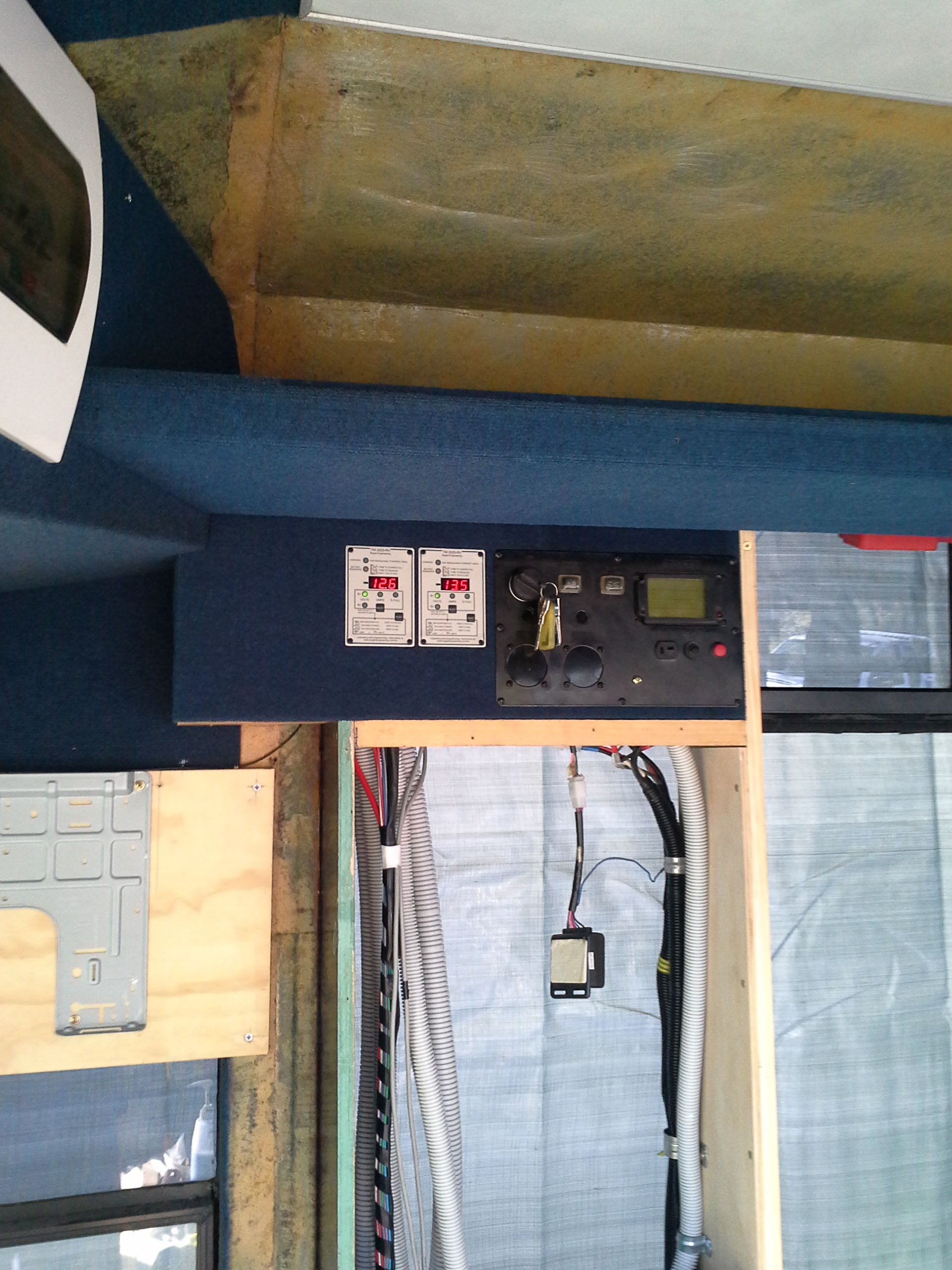
Generator Controls & the Battery monitors in the same panel of the Cabinet, the box hanging from behind the generator controls is for the wireless control of the generator.
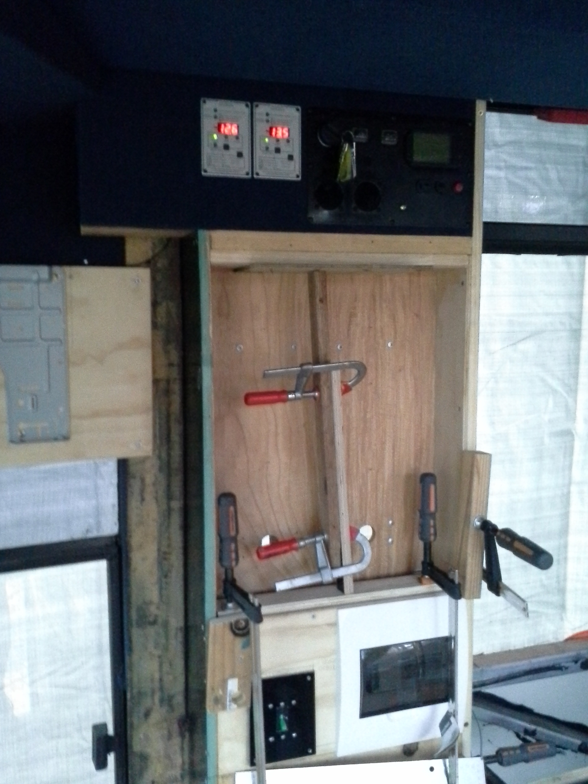
The recessed center compartment is to house the 2 Solar controllers, the NG rosewood ply is in the process of being applied.
