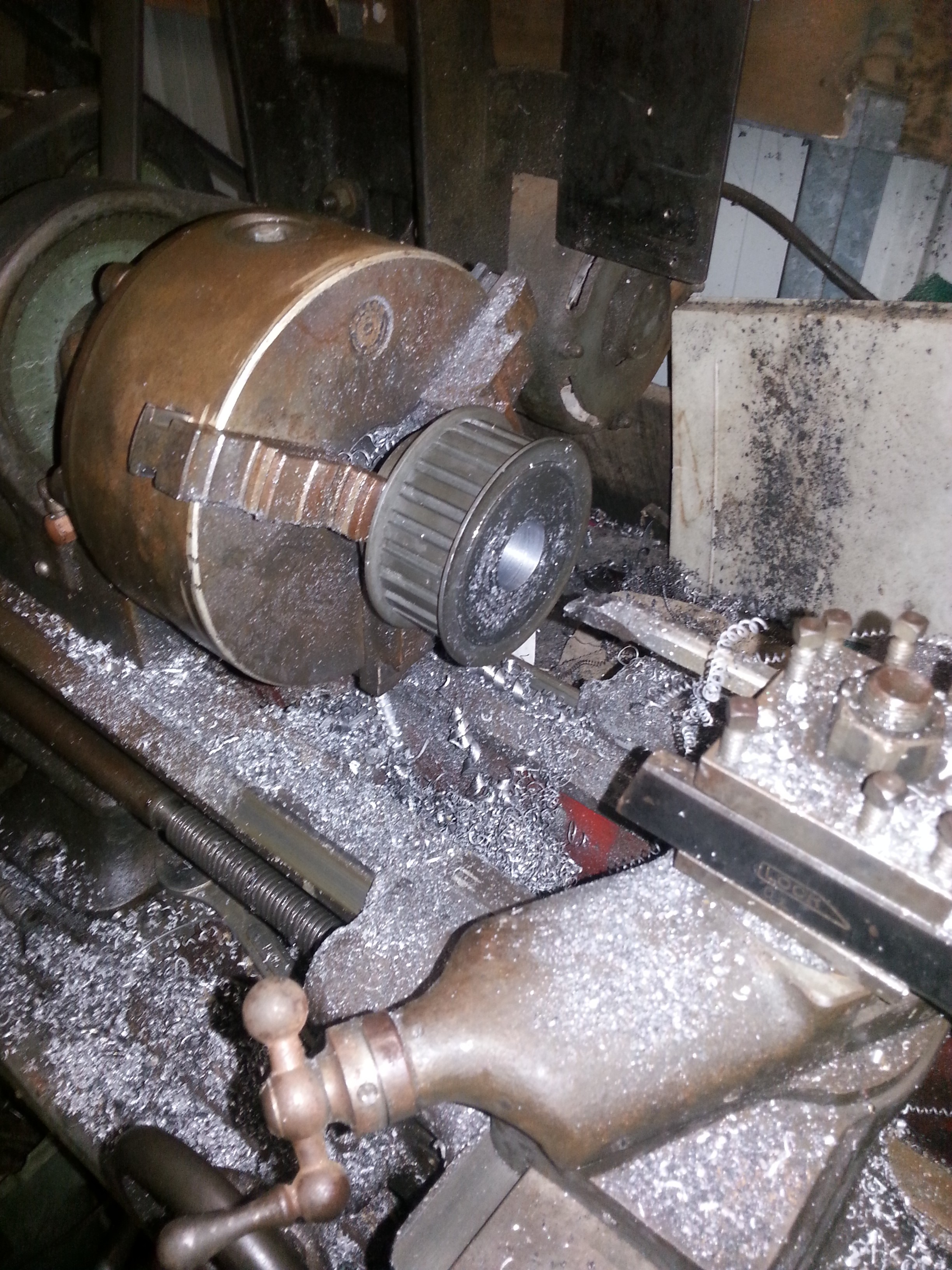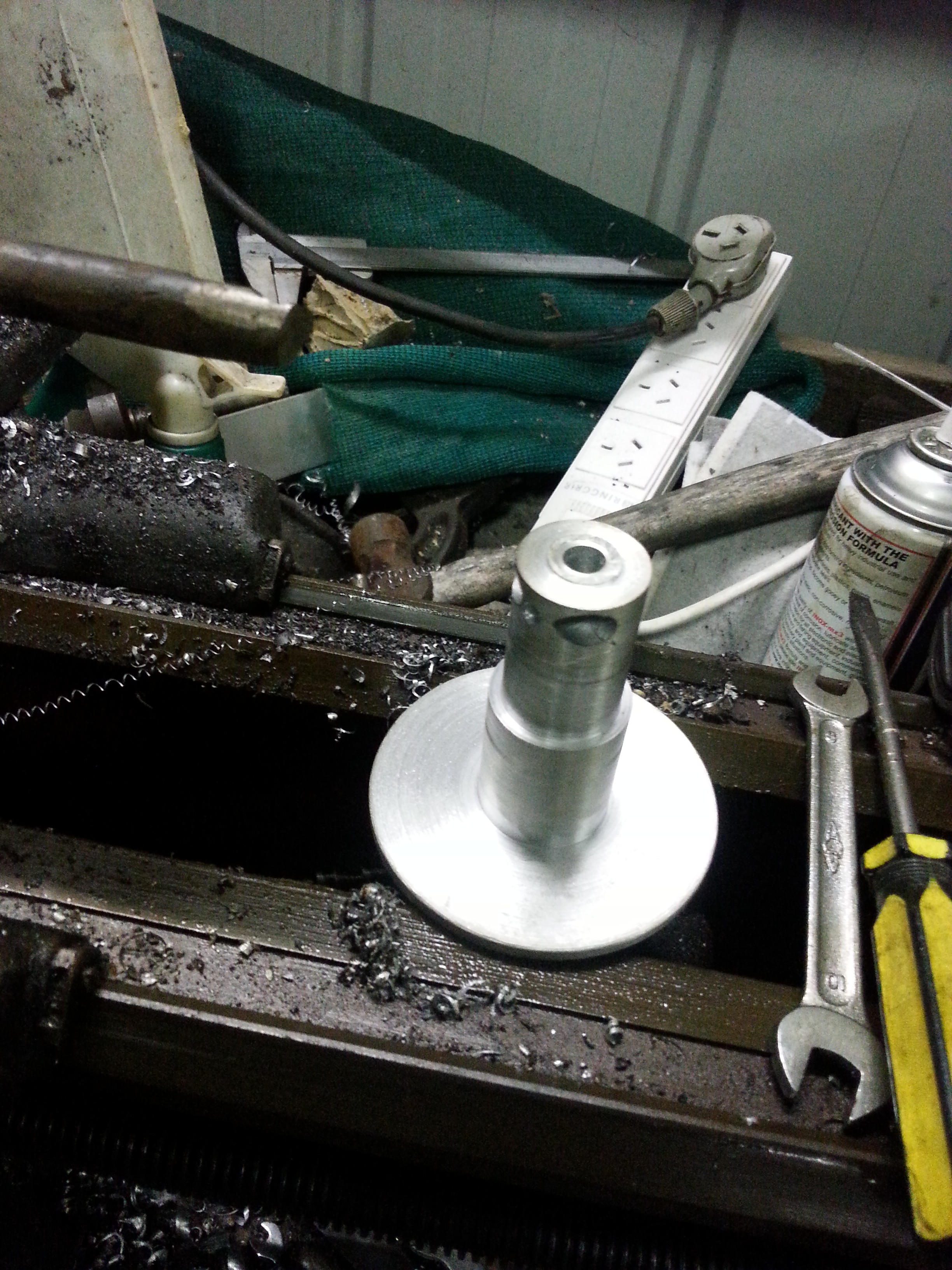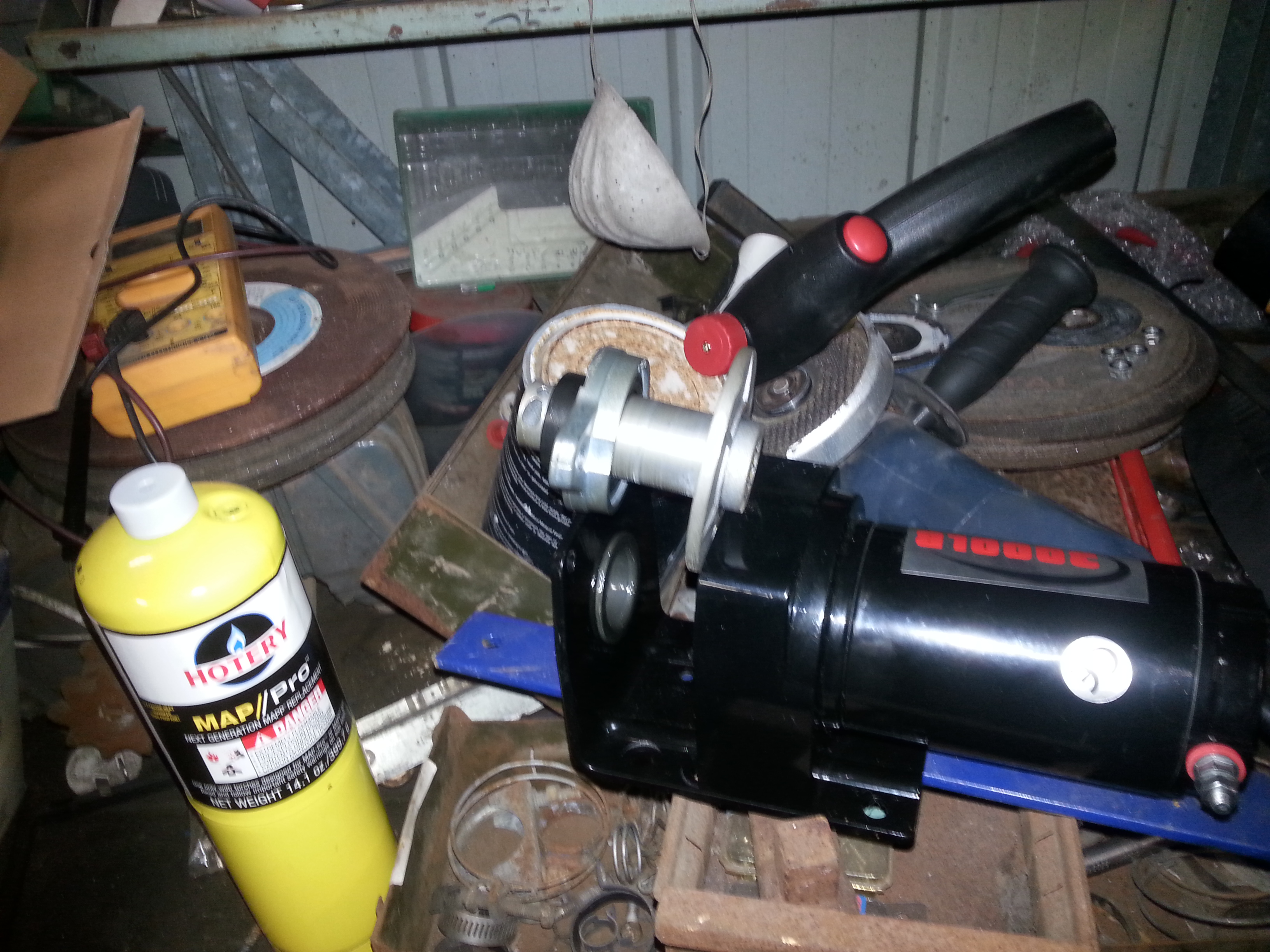
I have started to modify a Domestic water heater, as it is made of copper & in good condition it will be an easy modification. The unit has had 250mm cut out of its height & I will be adding 1 extra inlet & outlet ( 1 set for the Diesel water heater ) prior to Silver soldering the unit back together.
Once the mods are completed I can refit the outer case & re-insulate with 2 pack foam. The current 3600W element can then be replaced with a 1800W unit & the Hot water unit will be ready to fit.
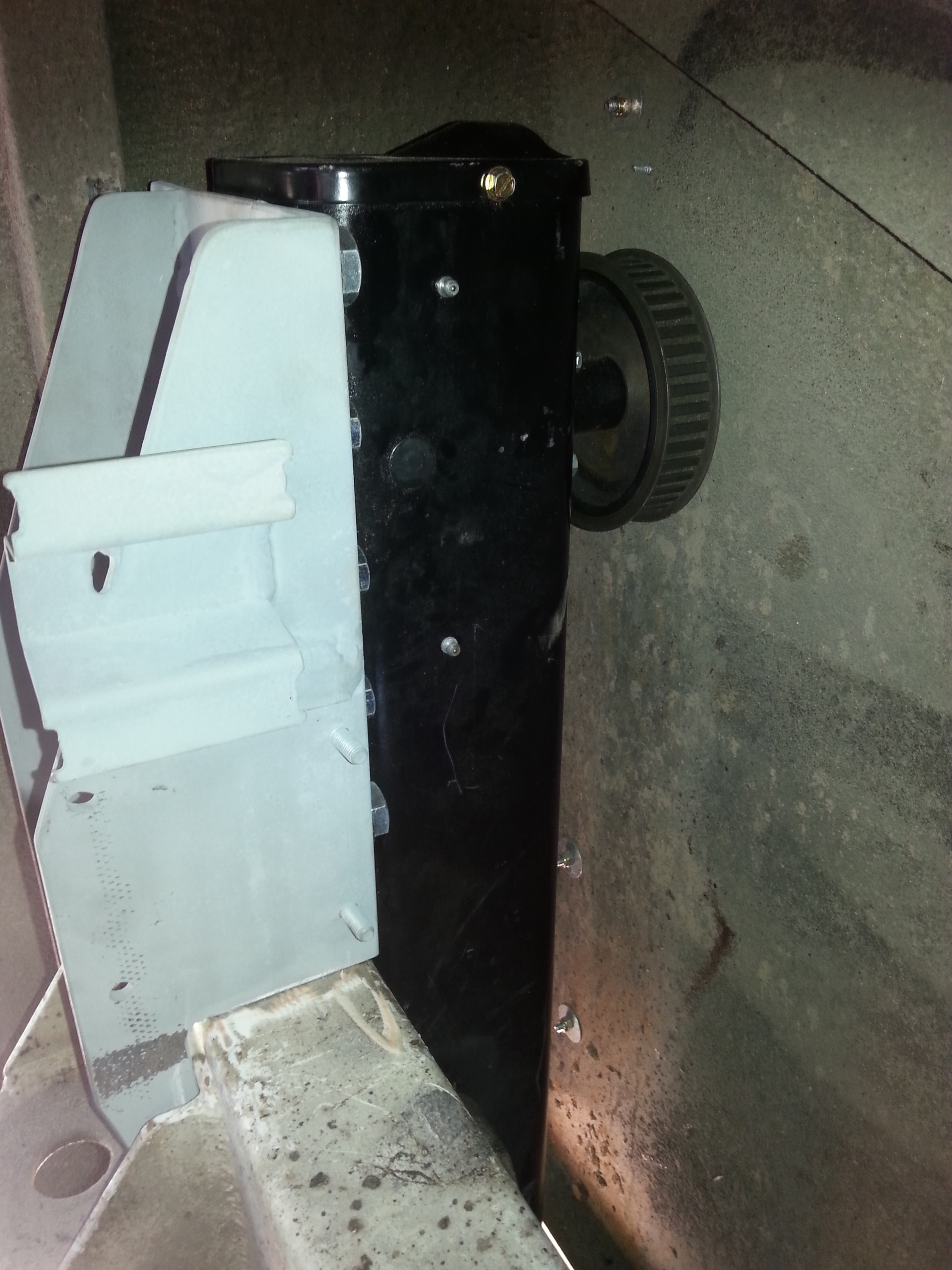
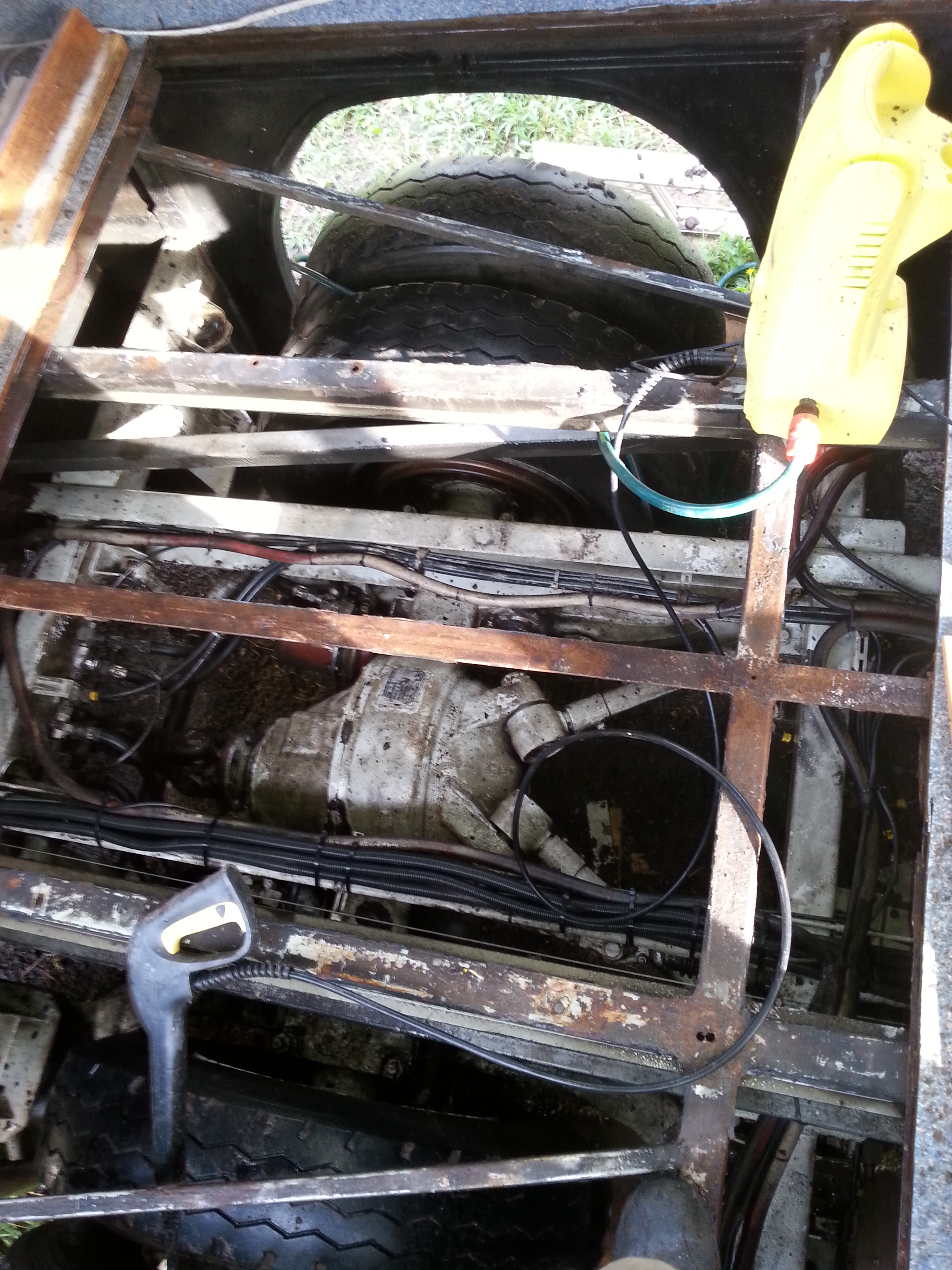
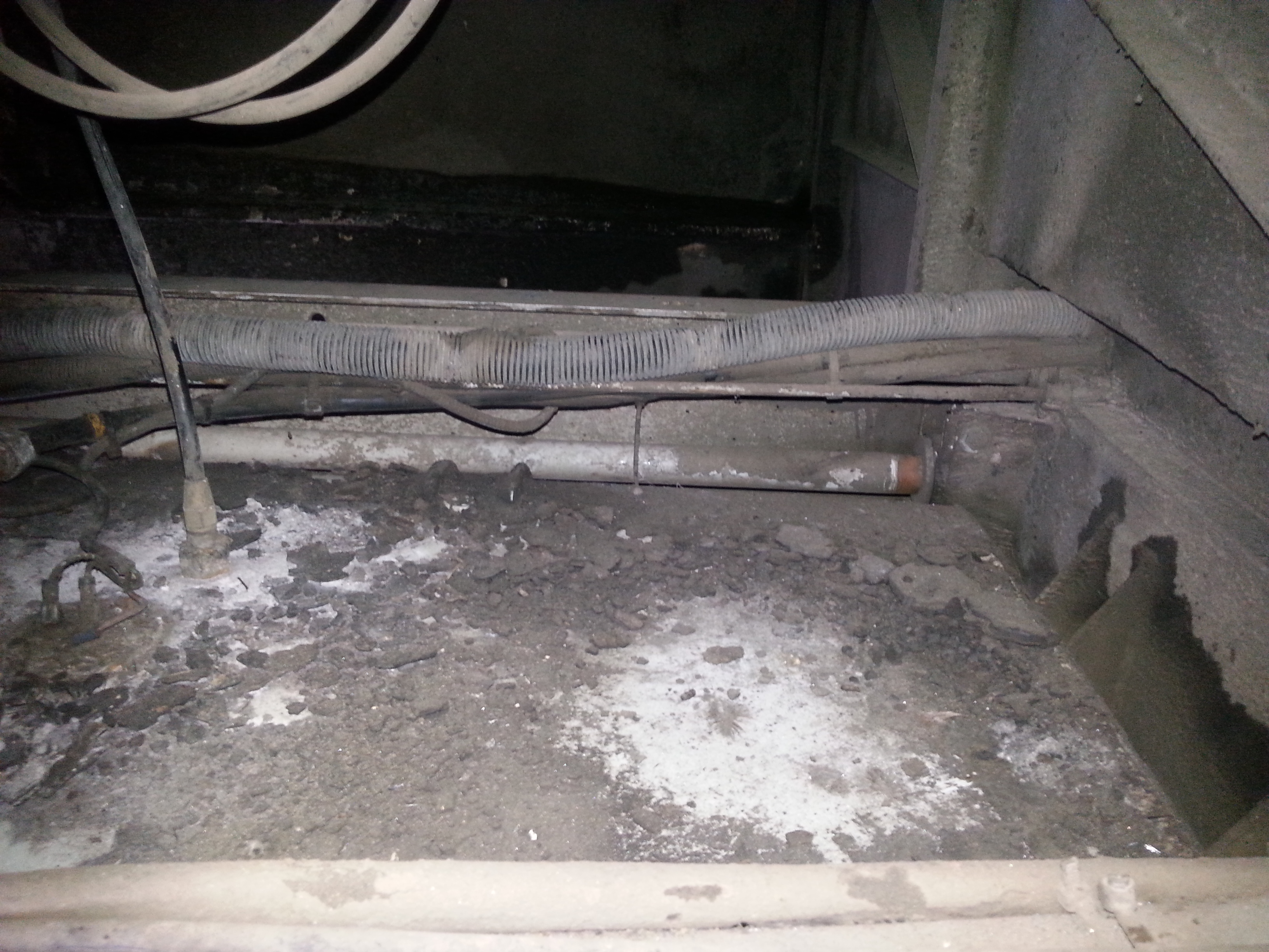
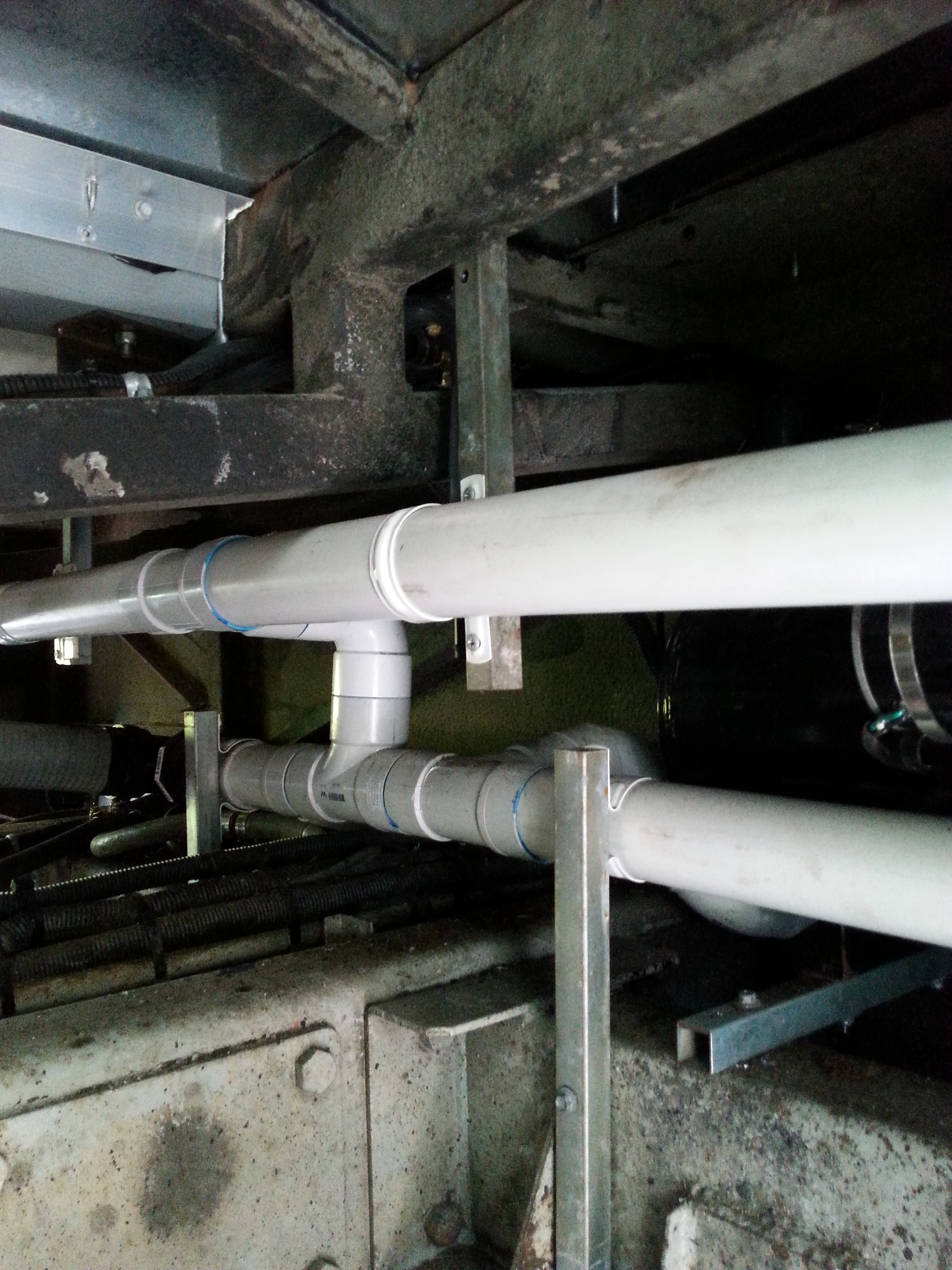
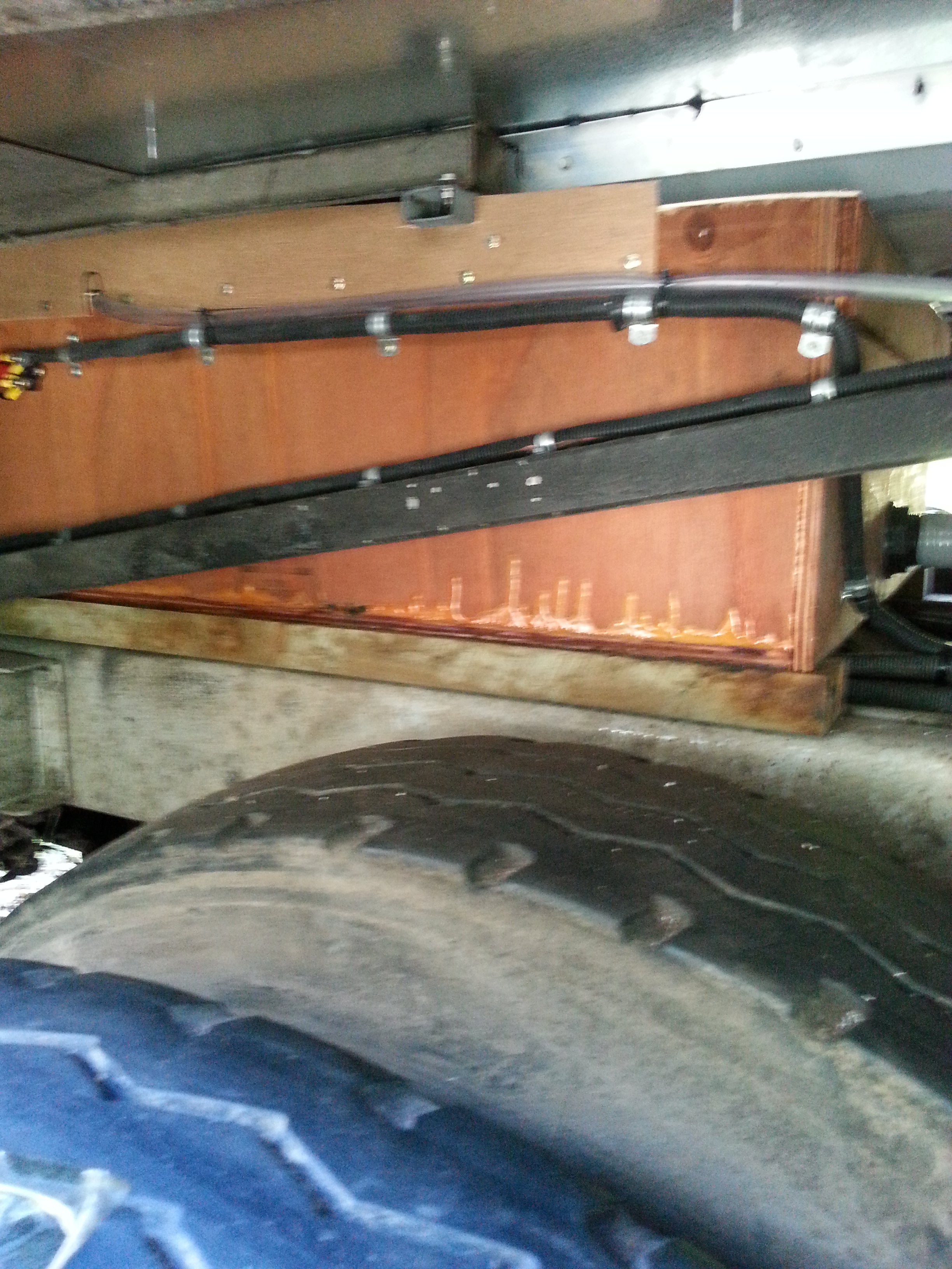
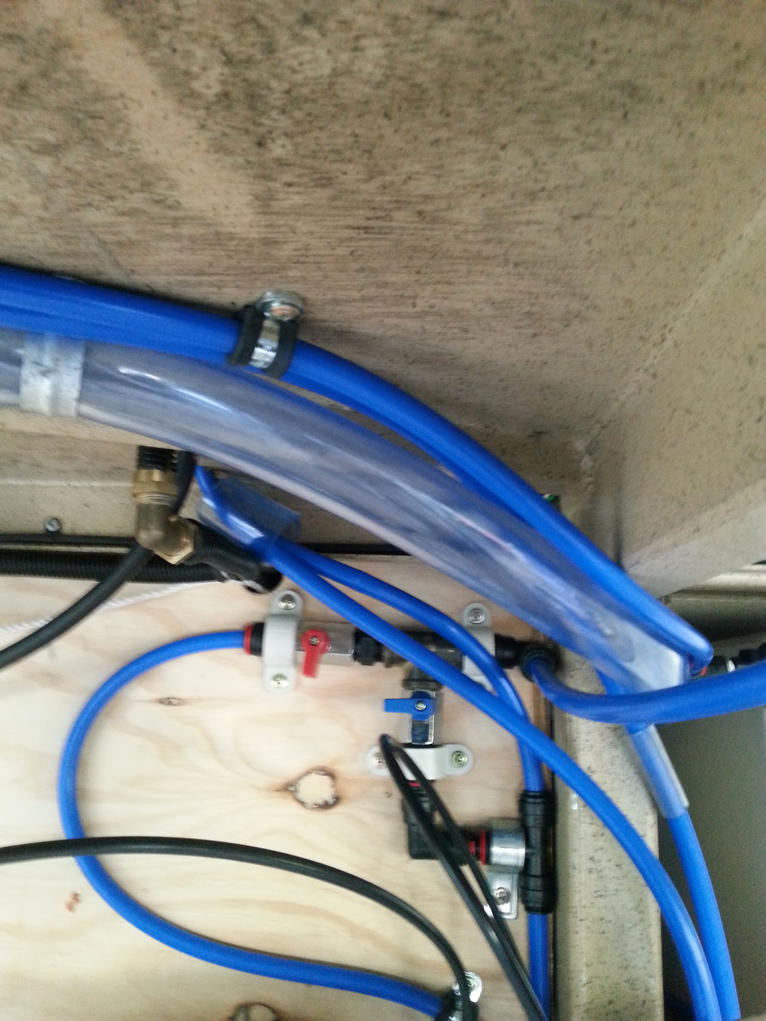
The Diesel water heater has now been mounted inside the R/H rear wheel arch over the Air Bag system, the plumbing has been completed & is ready for connection to the Hot Water system. The exhaust pipe for the unit has been made to exit the Vehicle in front of the rear wheel just below the body work.
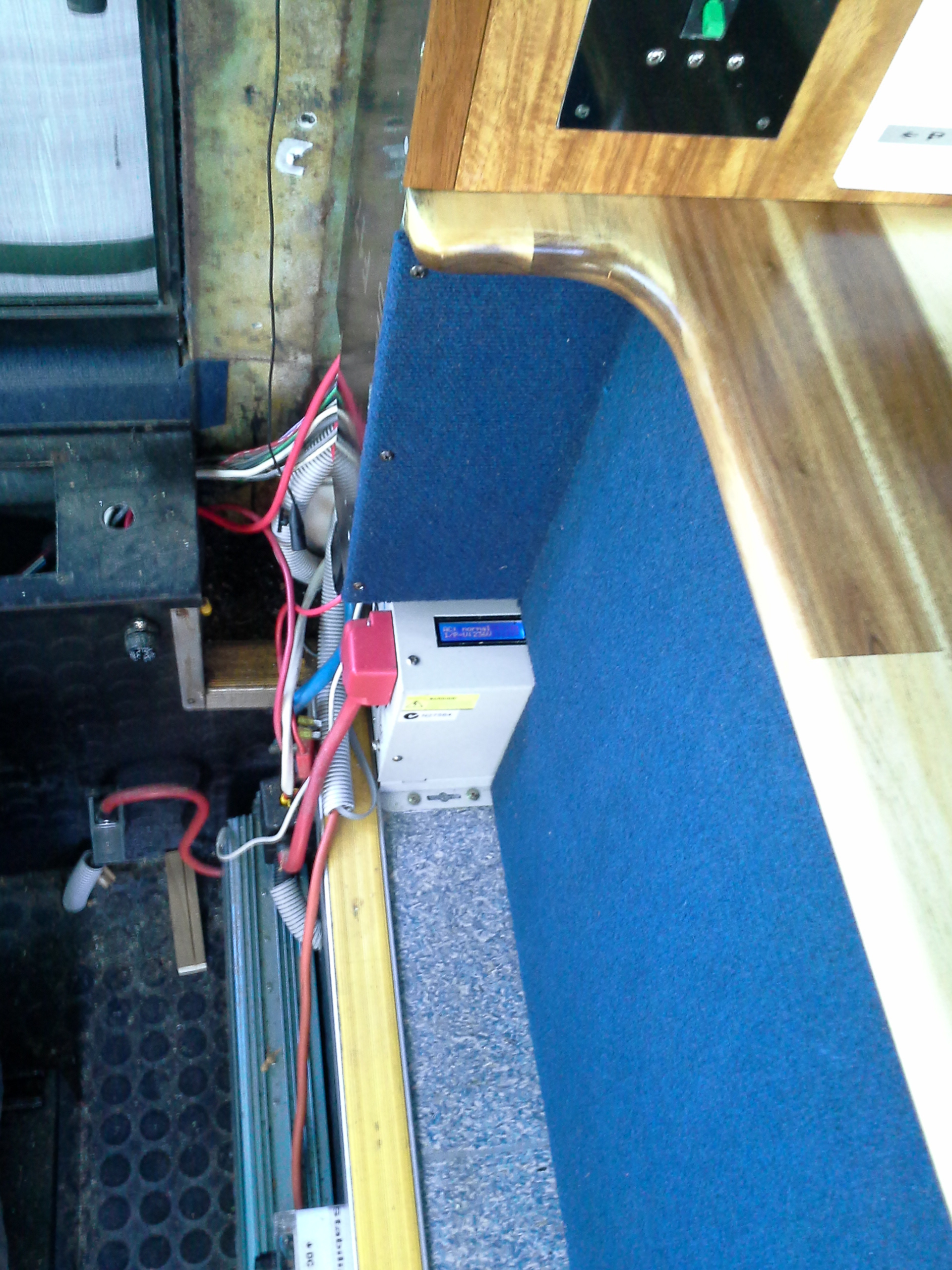
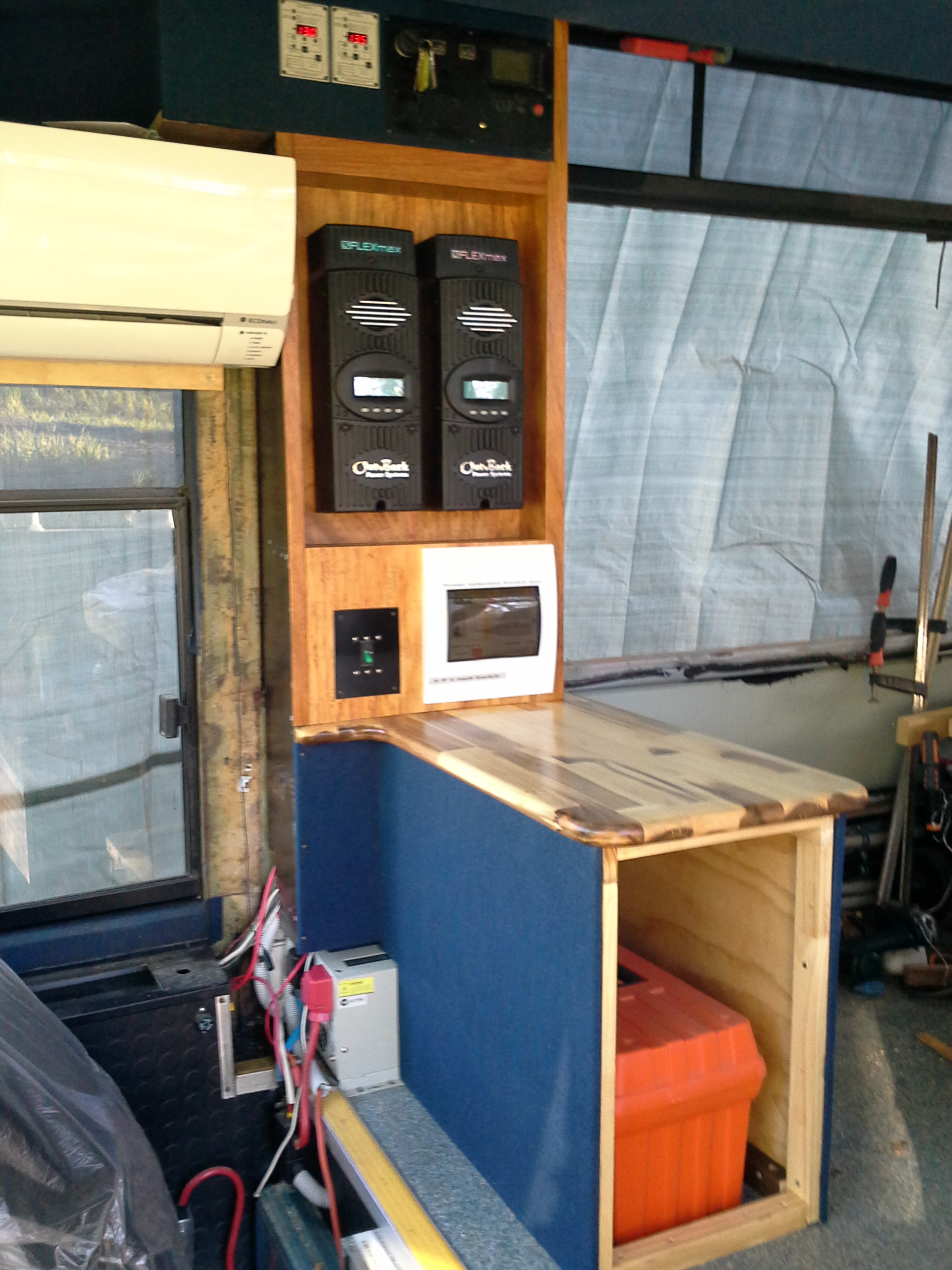
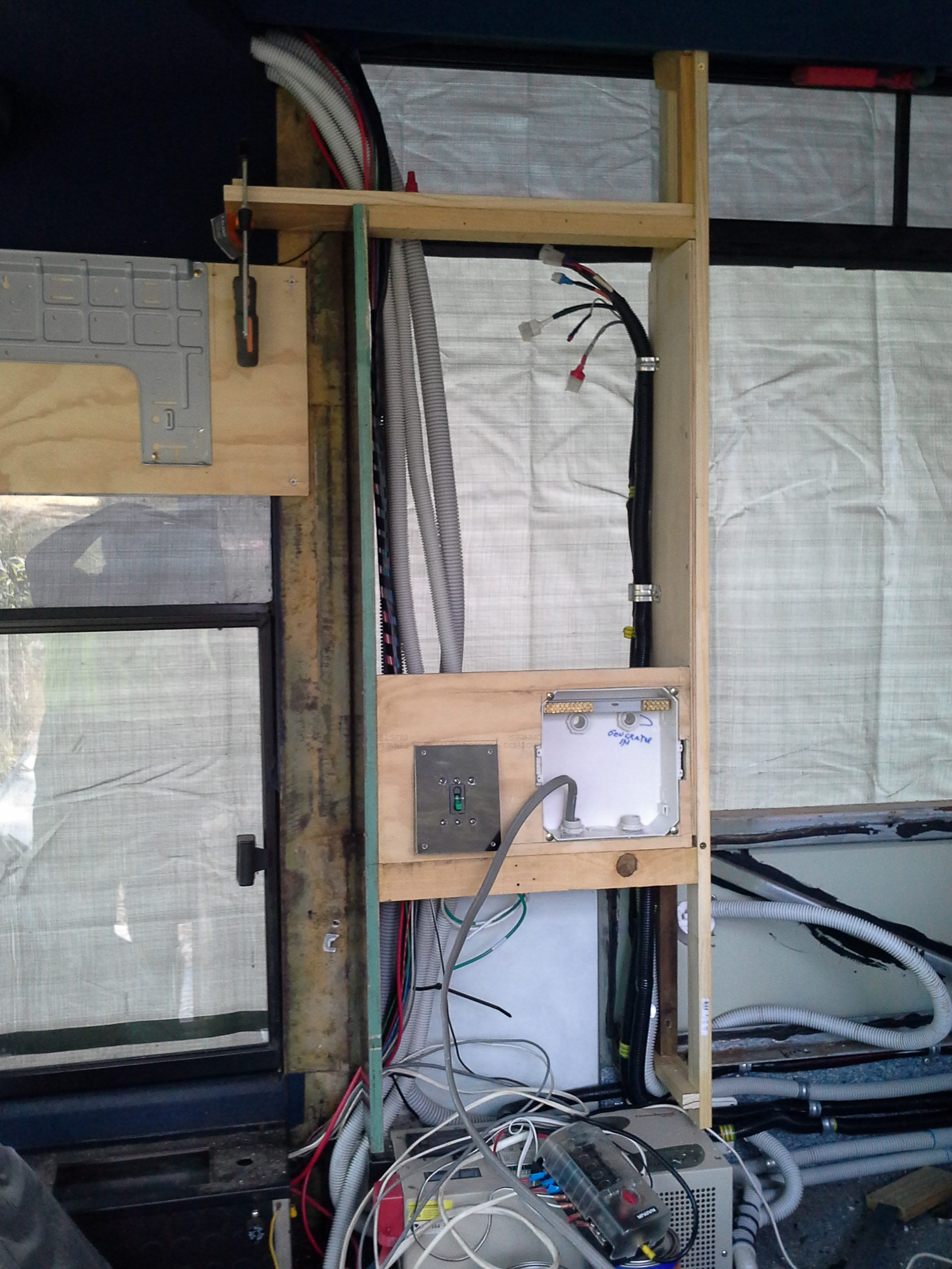
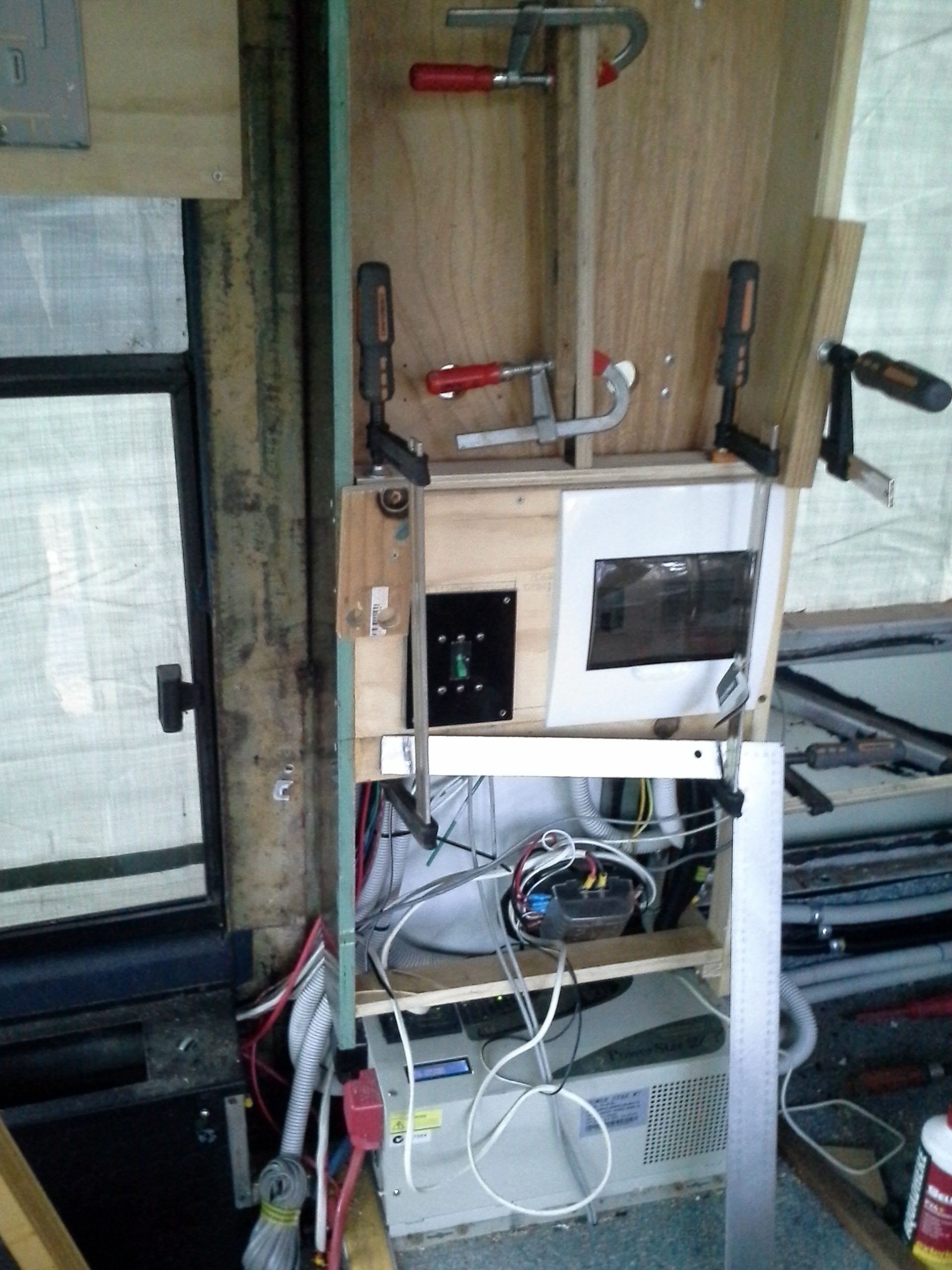
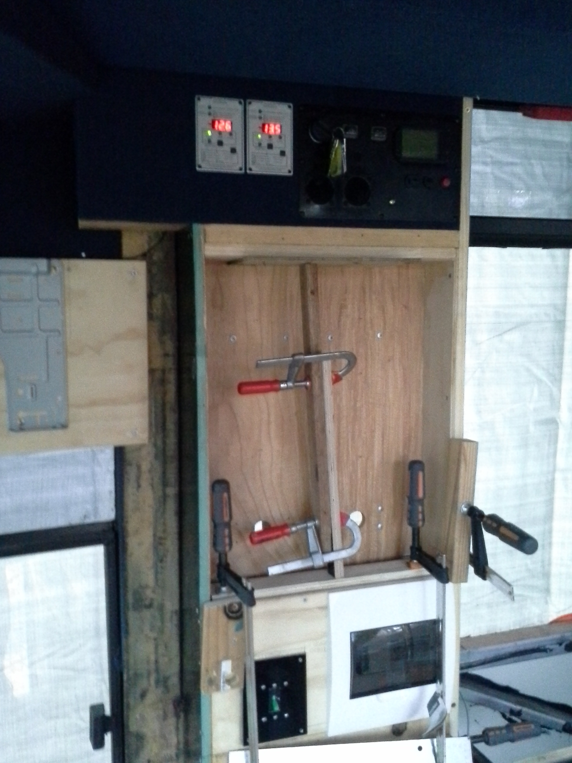
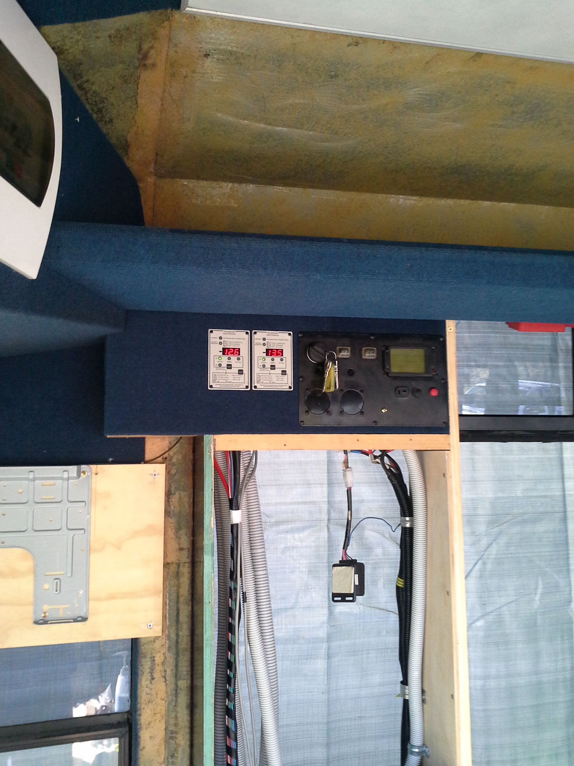
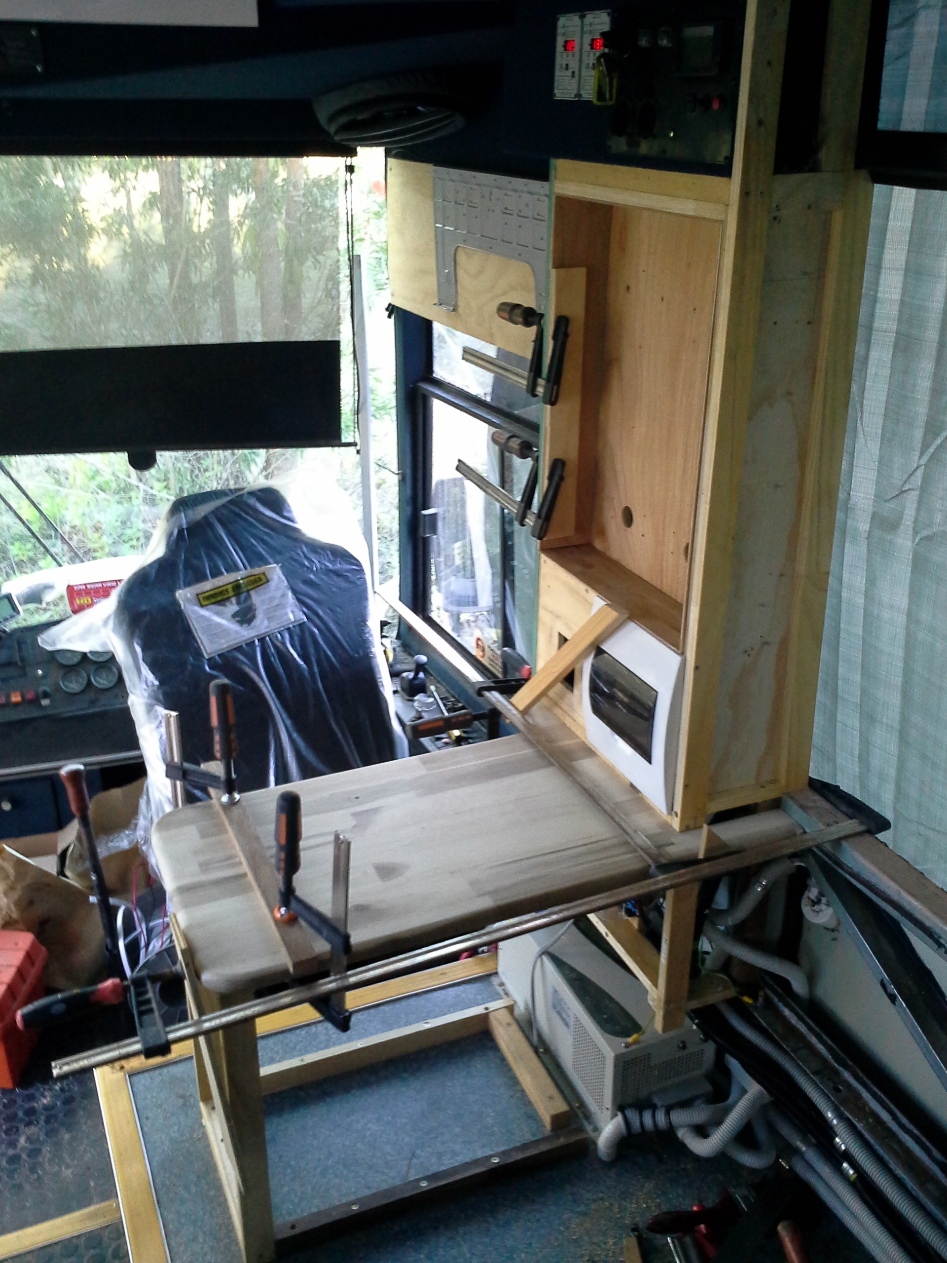
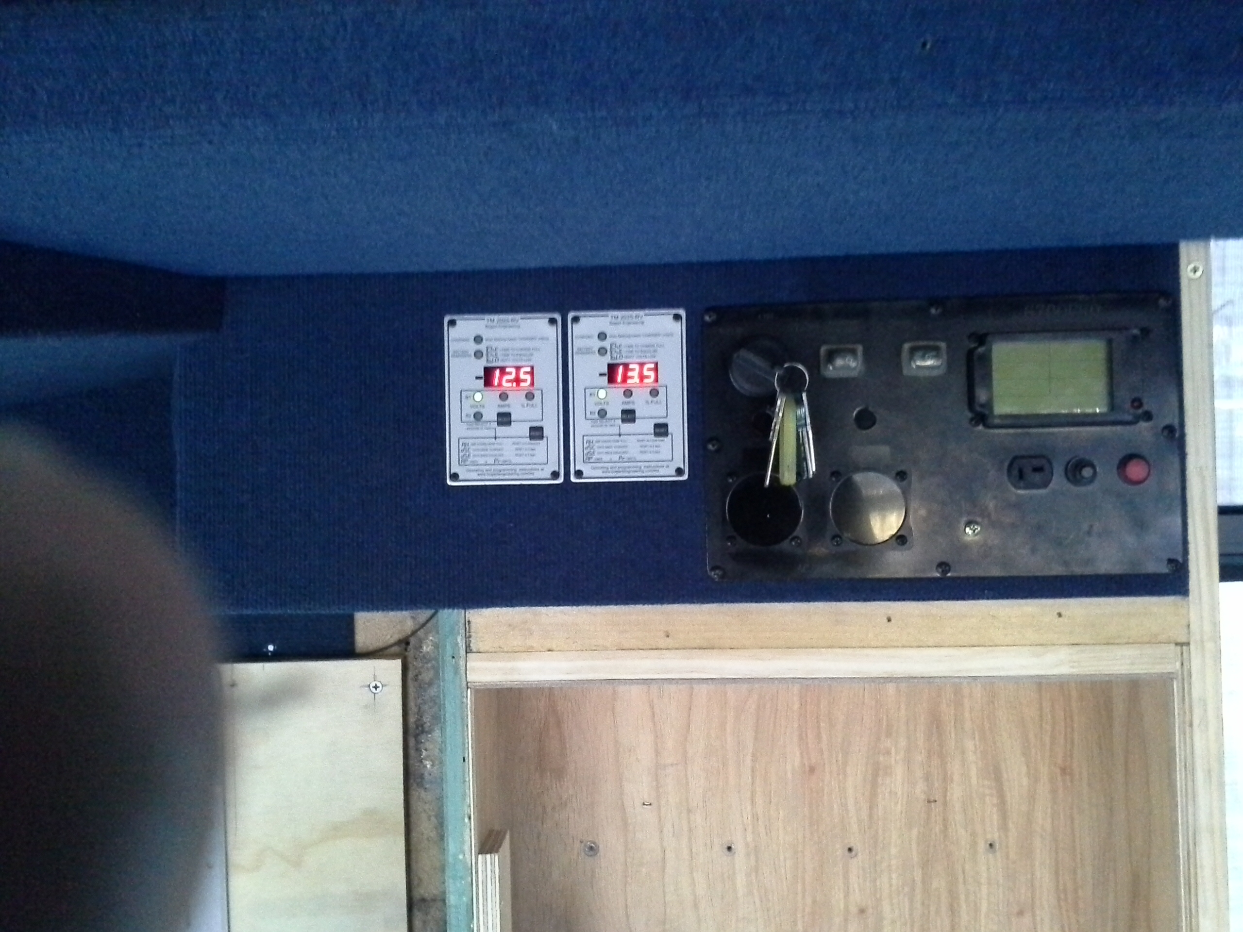
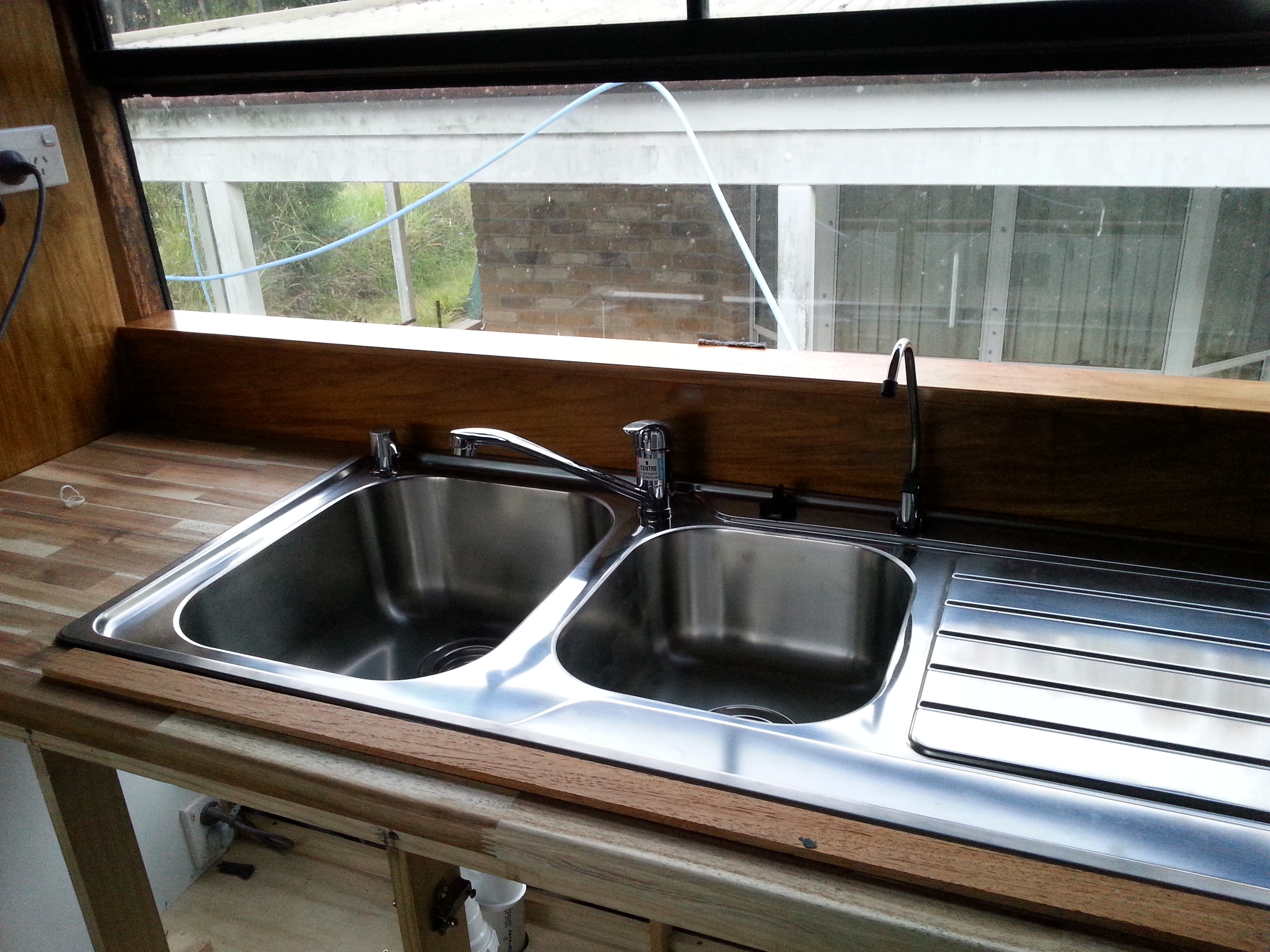
The Electrical controls have been fitted to the Kitchen side of the Pantry wall just below the ceiling, from this point the circulation pump & the Diesel heater can be started, stopped or set to Auto.
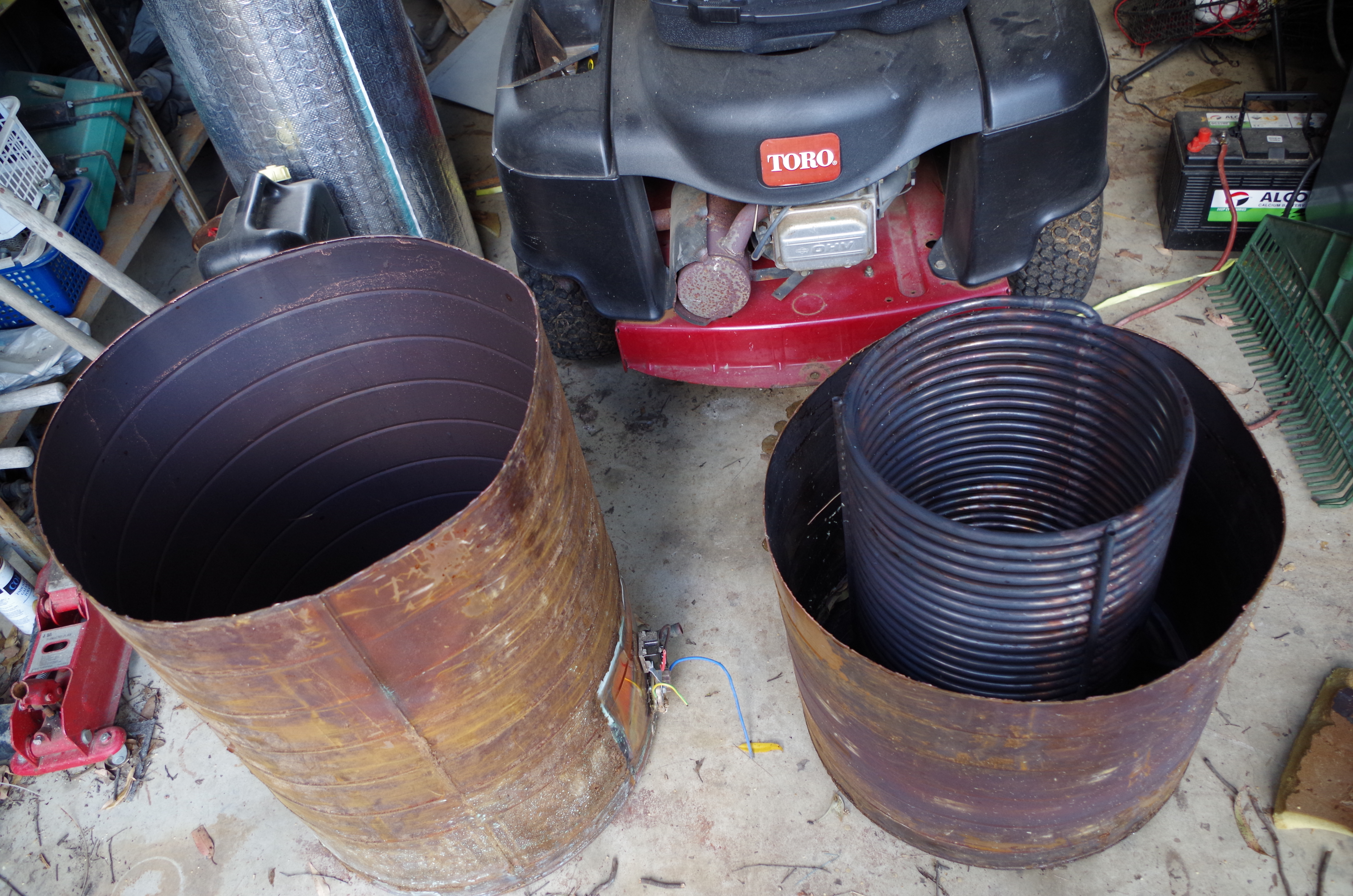
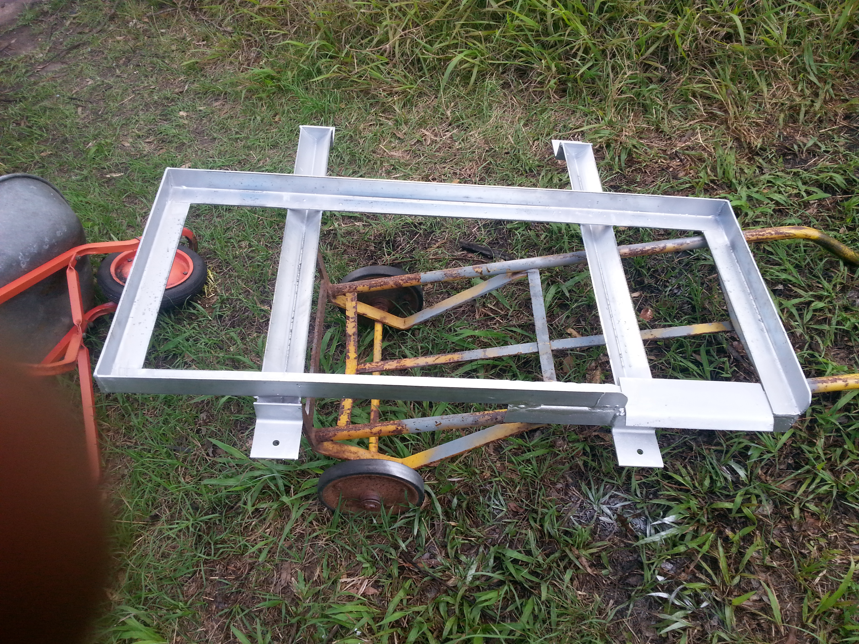
The 2 halves of Hot water tank, Unit on the left is to have 250mm removed to reduce the capacity.
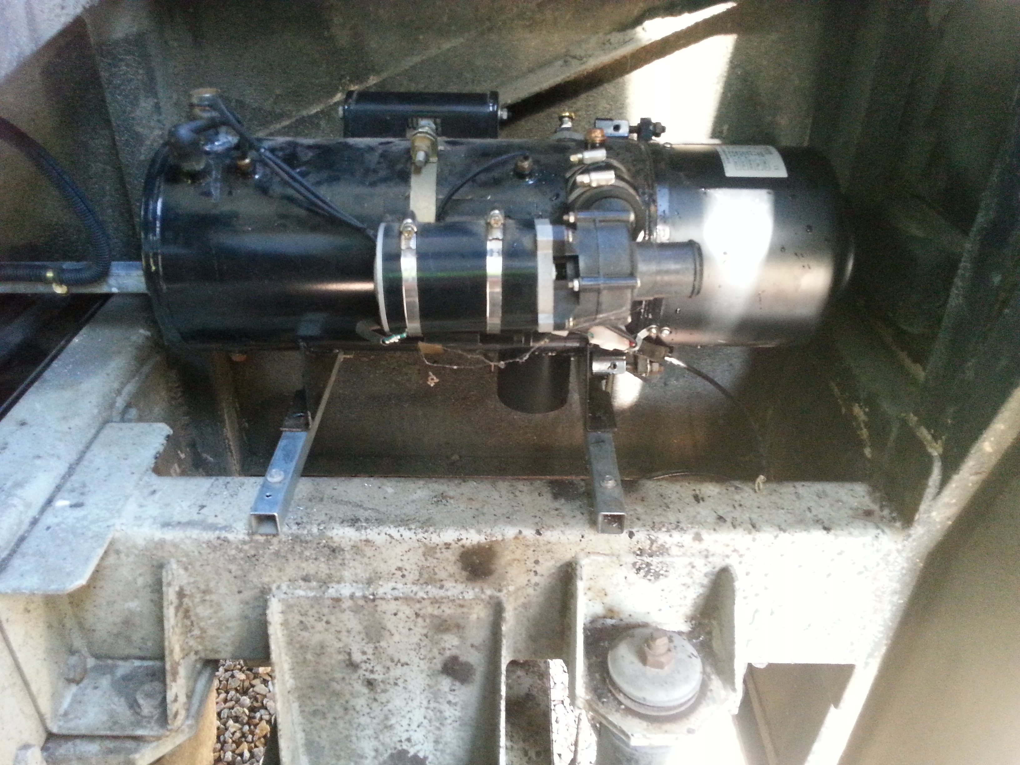
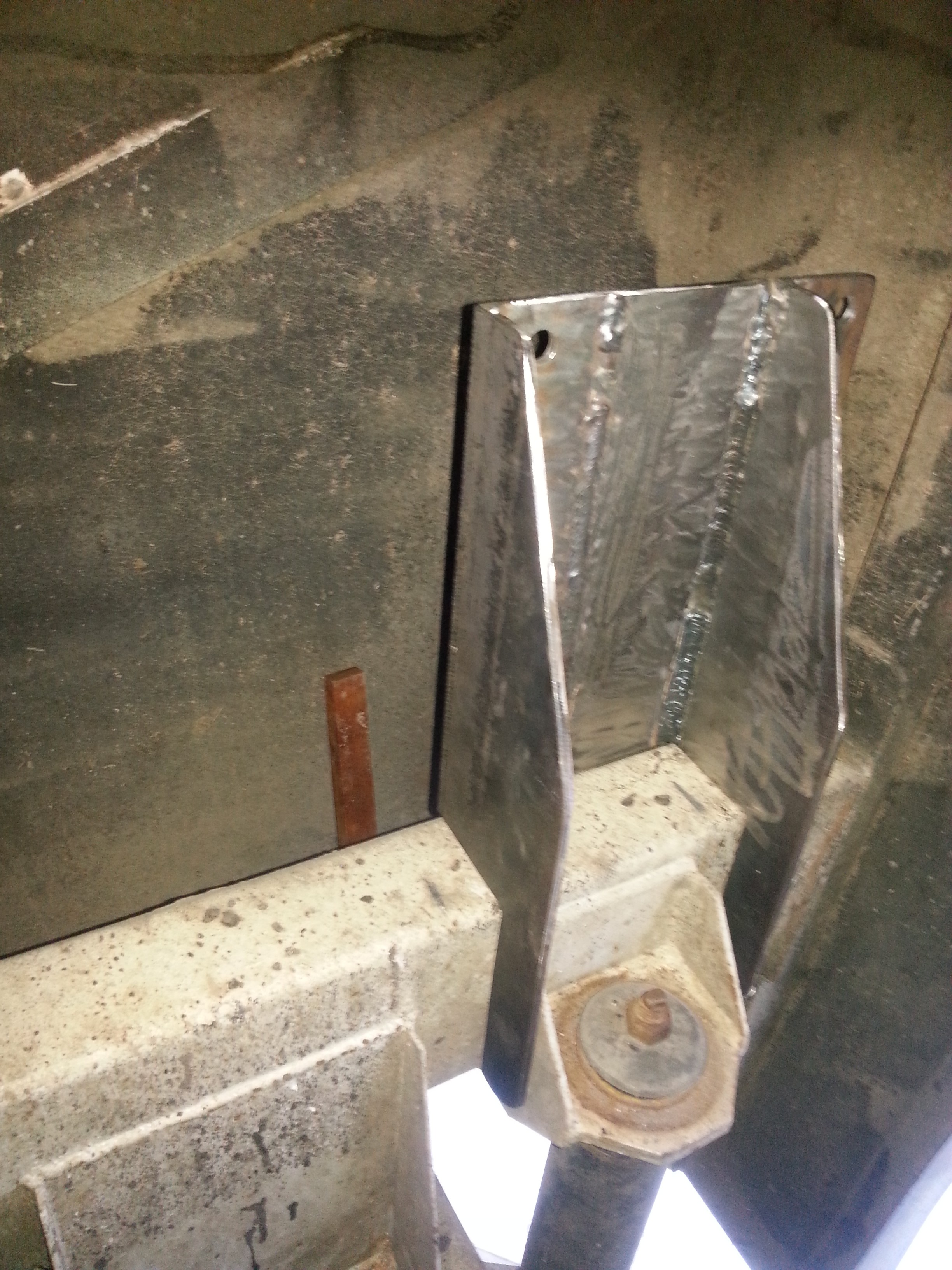
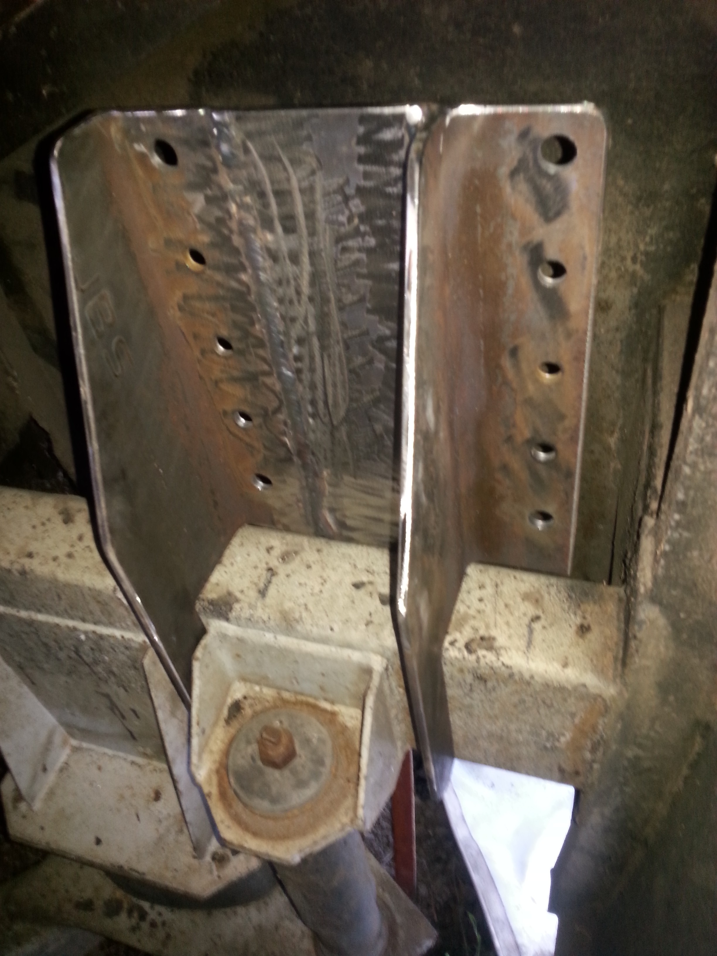
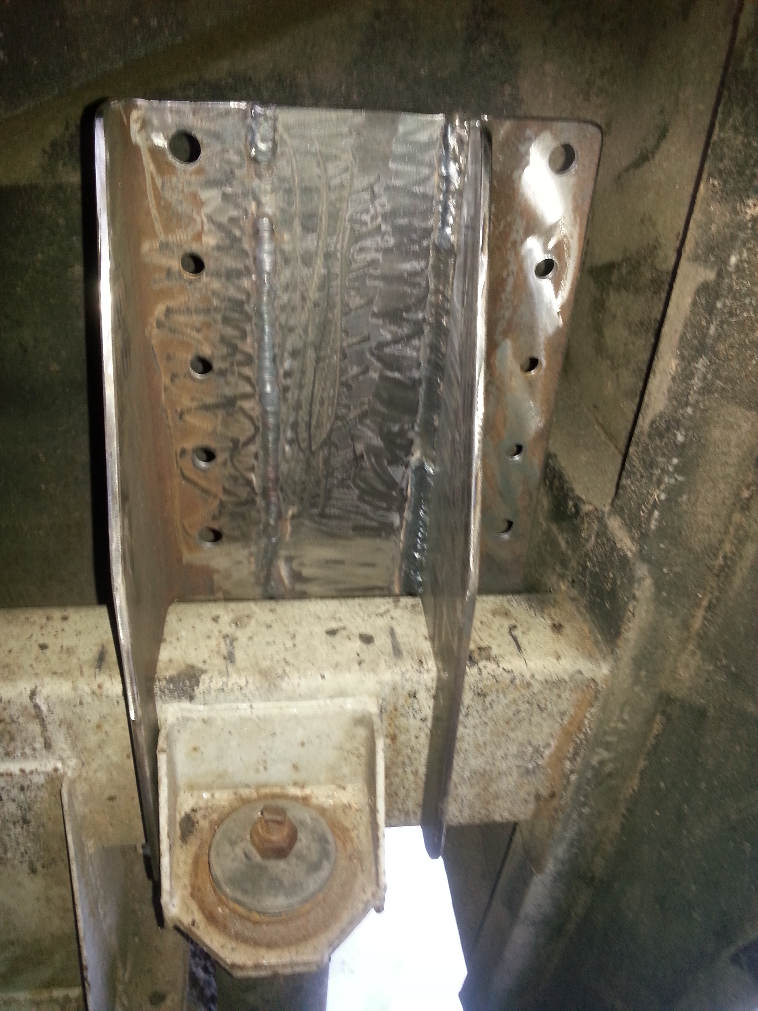
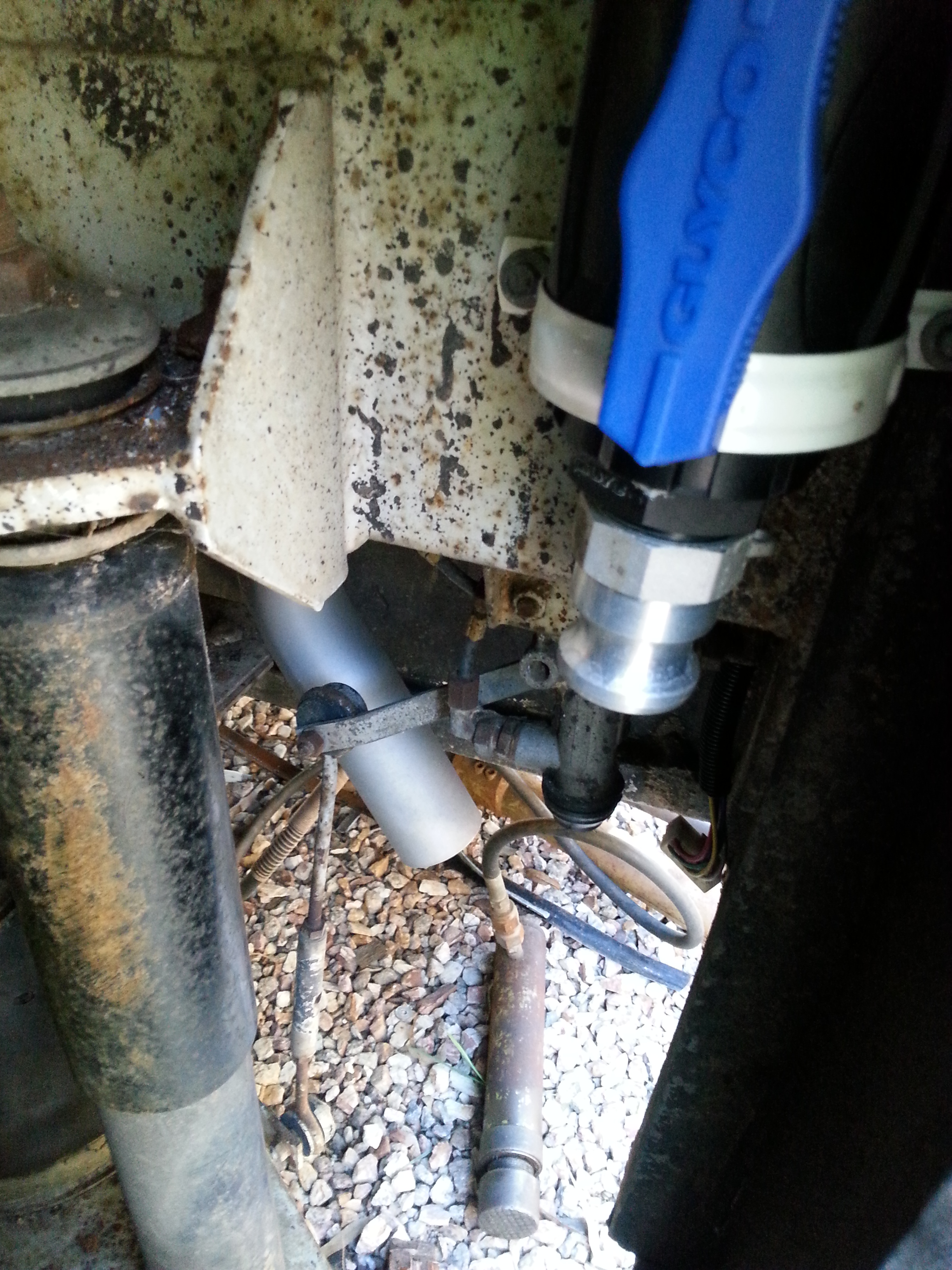
Diesel unit on mounts over the R/H front Air Bag of rear suspension.
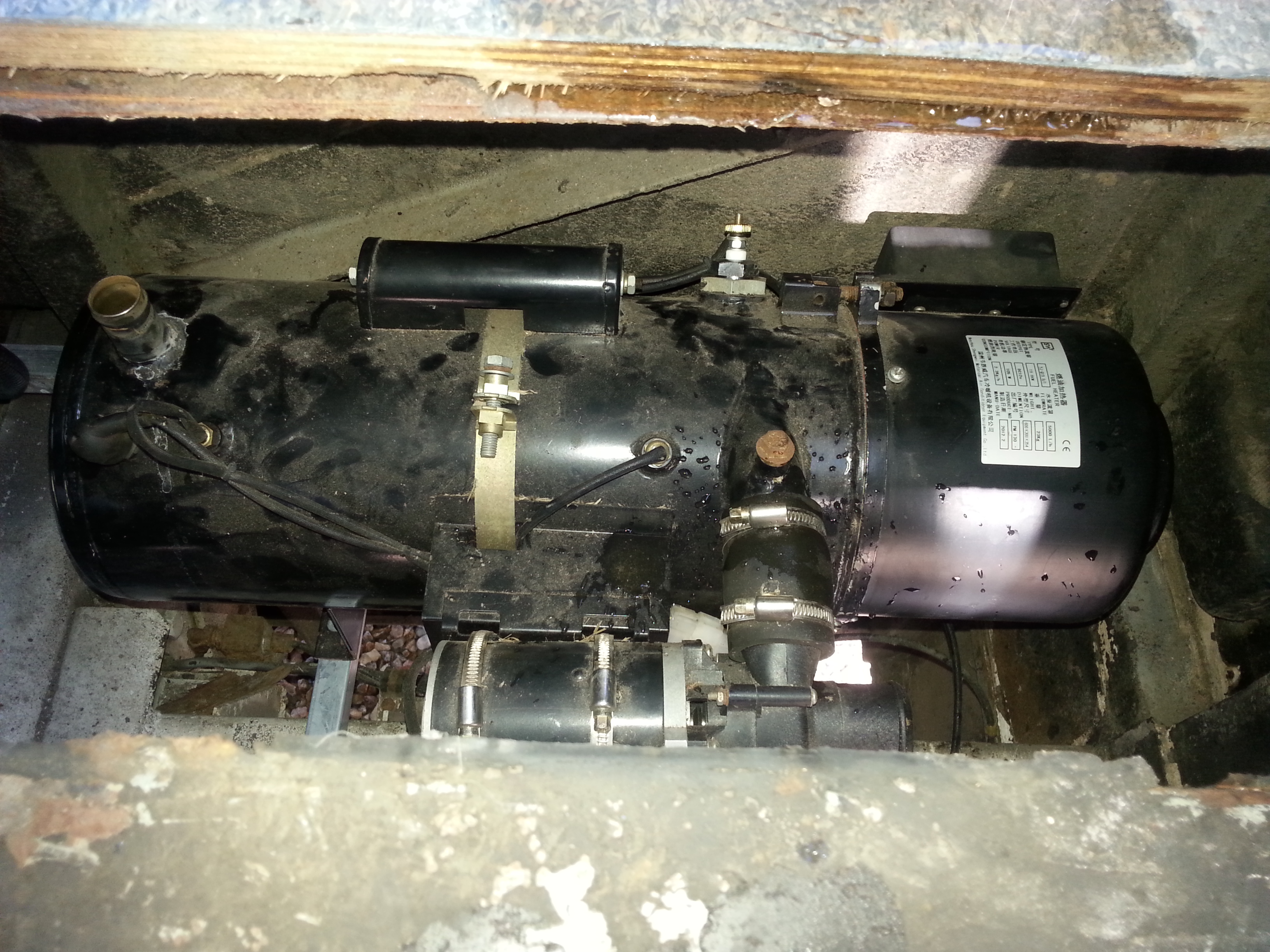
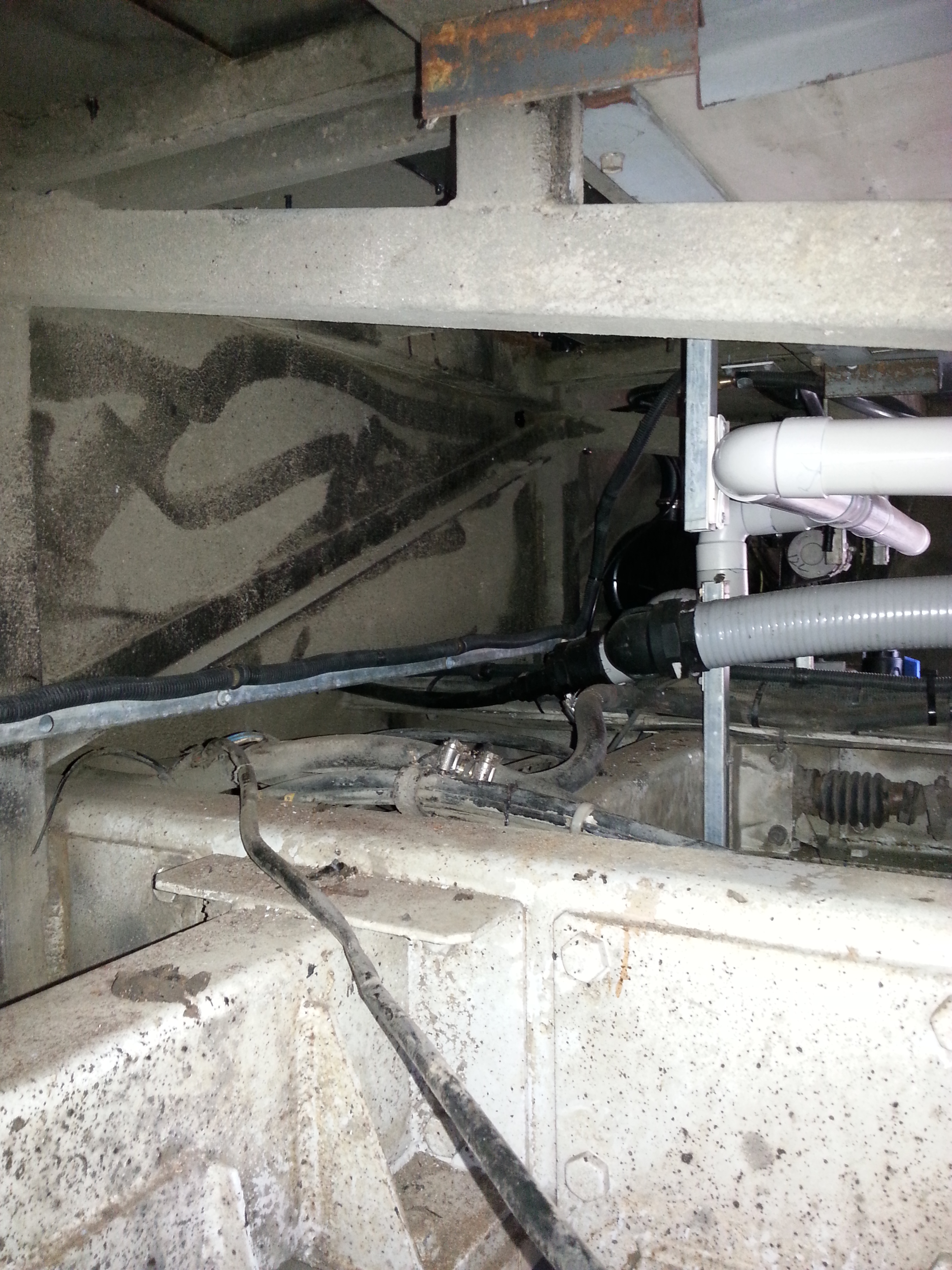
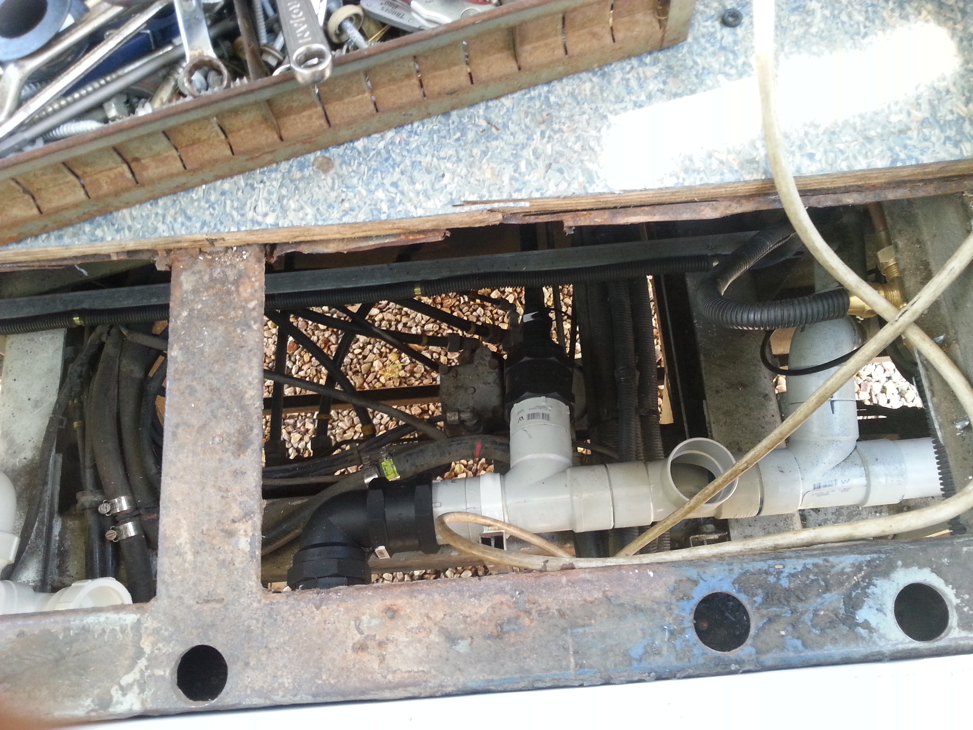
View of the Diesel Hot water unit from over the Driver side rear wheel.
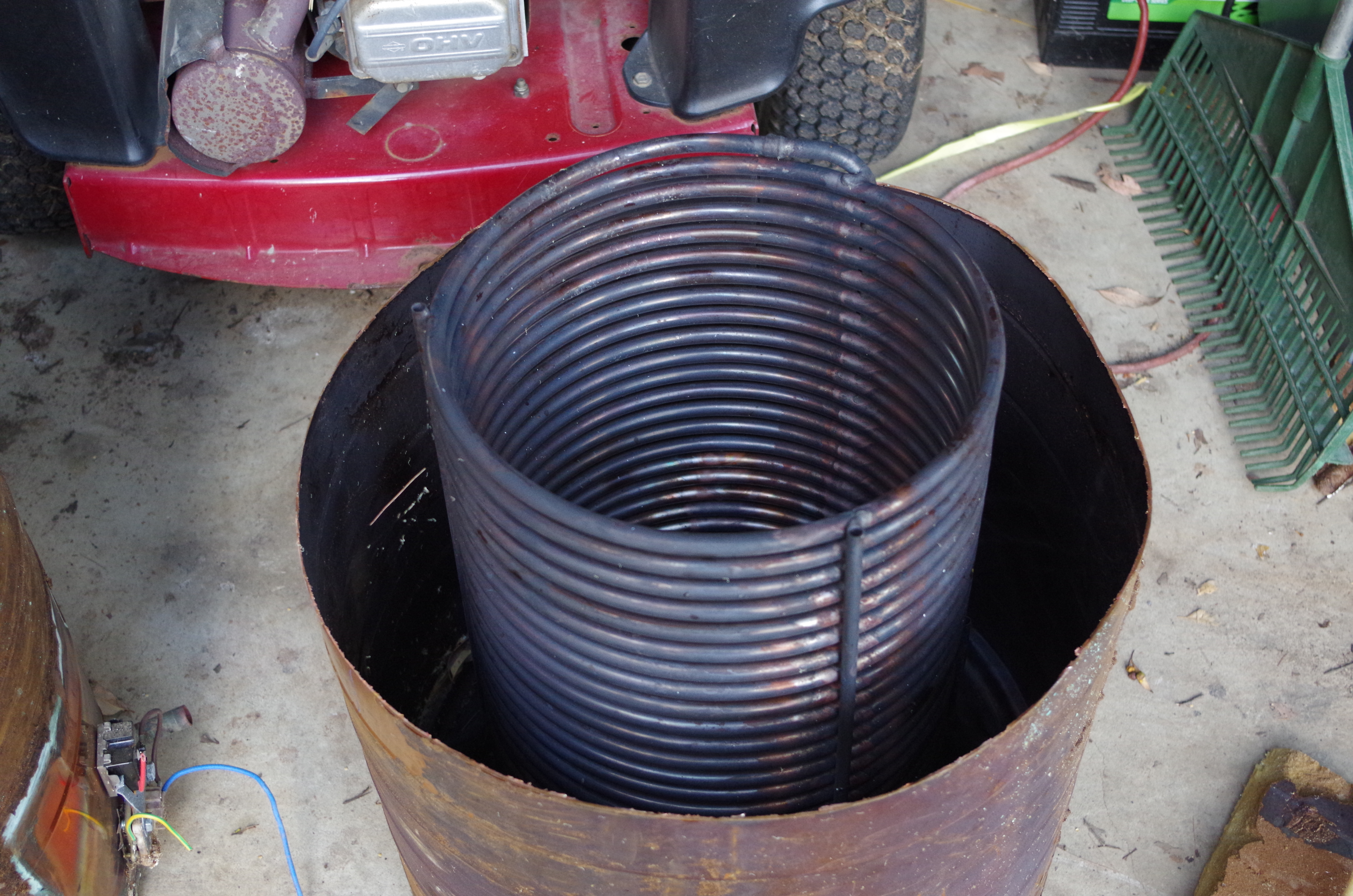
The 315L hot water unit opened up ready for modifications.
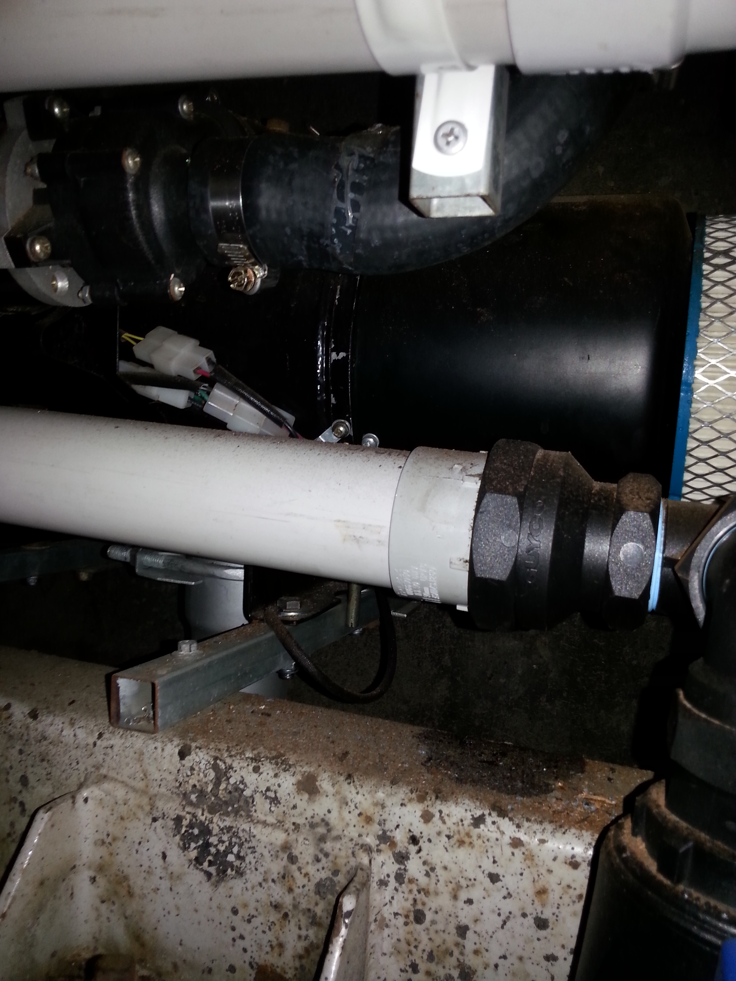
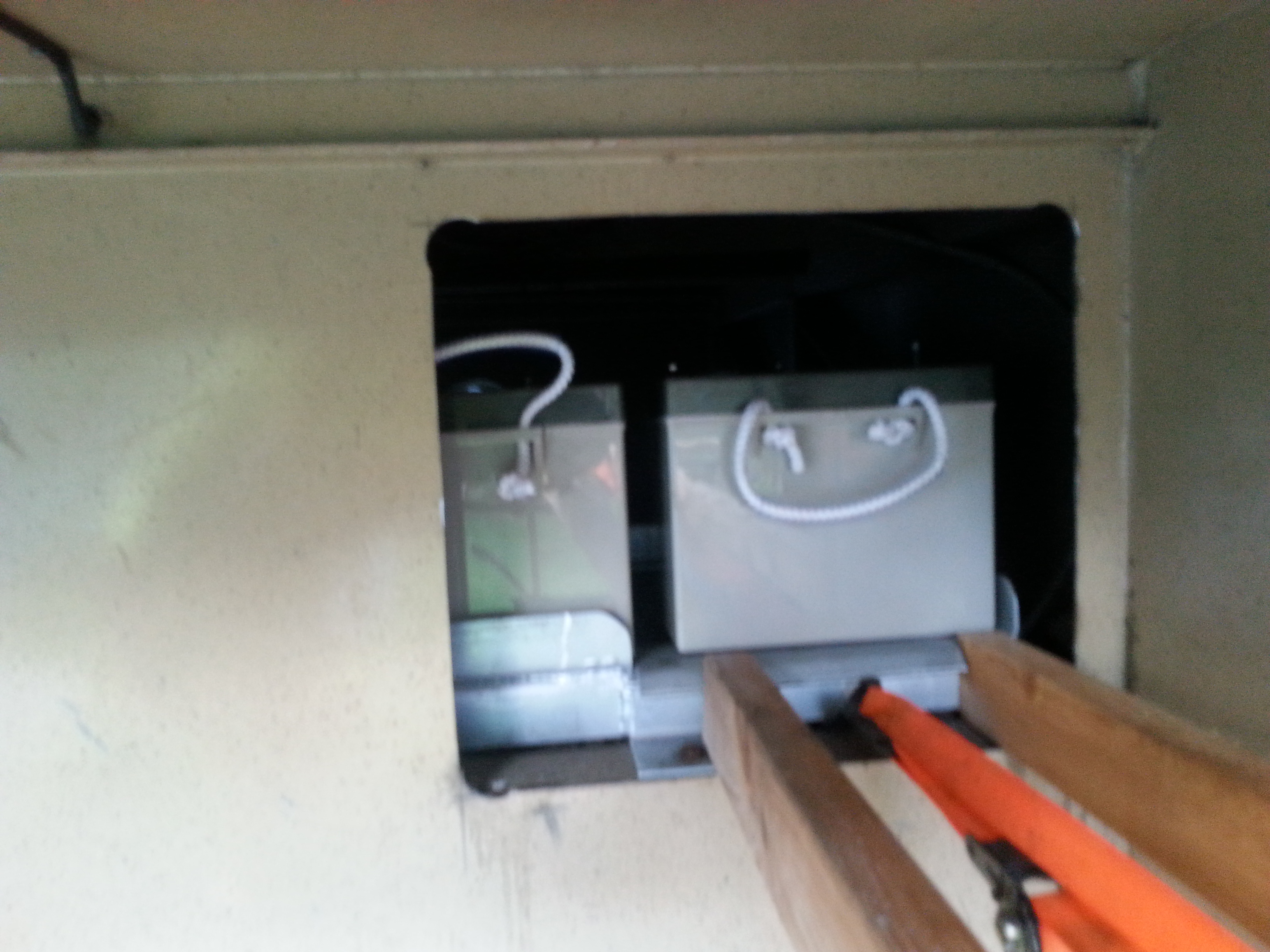
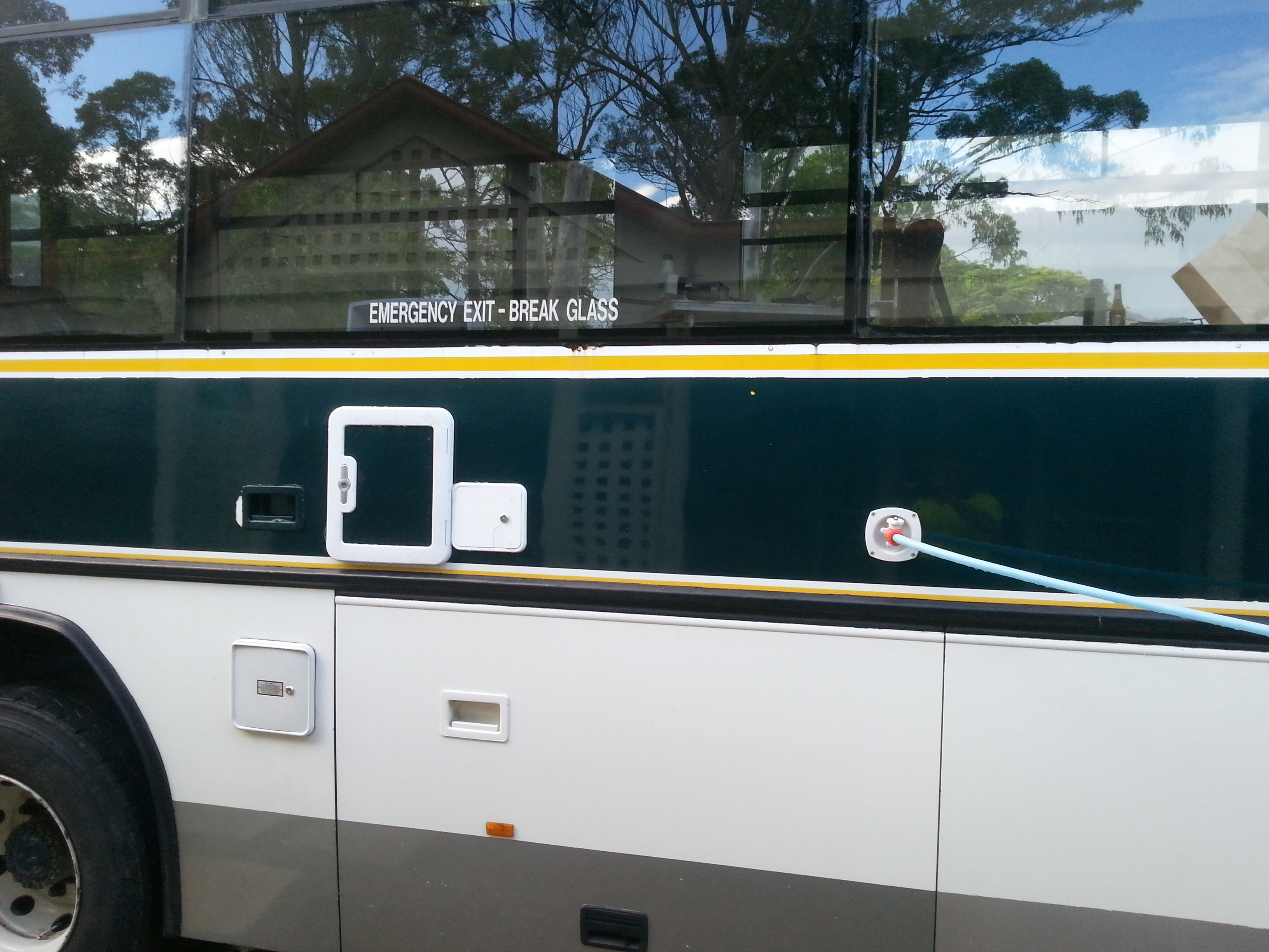
Diesel hot water unit visible behind the plumbing, due to the position of this unit I have added an Air Cleaner to the intake. The Air Cleaner can be acessed through a hatch in the side of the RV.

Lower Left Hatch is for Access to Diesel heater filter.