Stabilizer system mountings & installation.

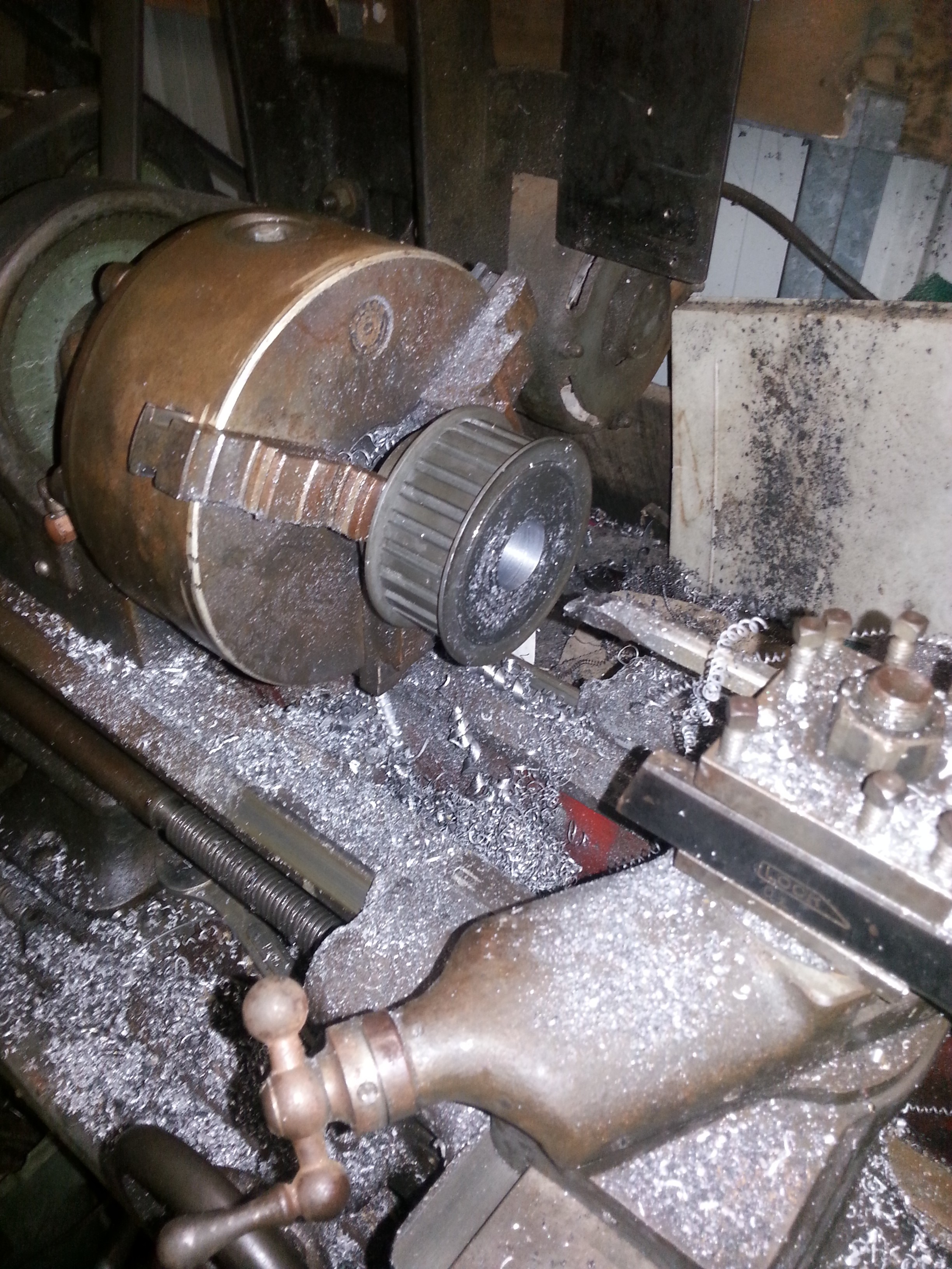
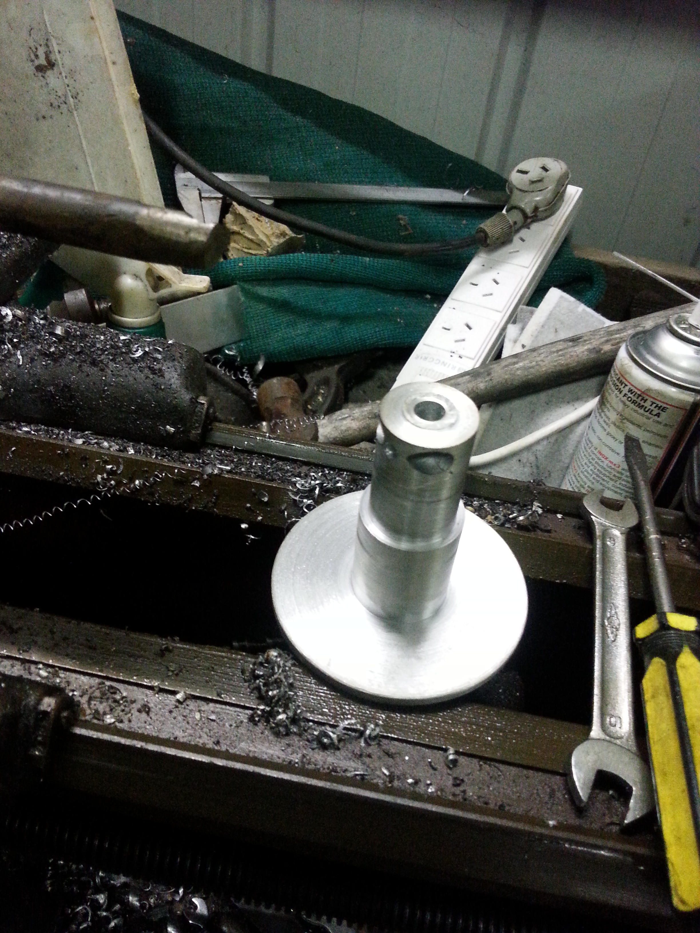
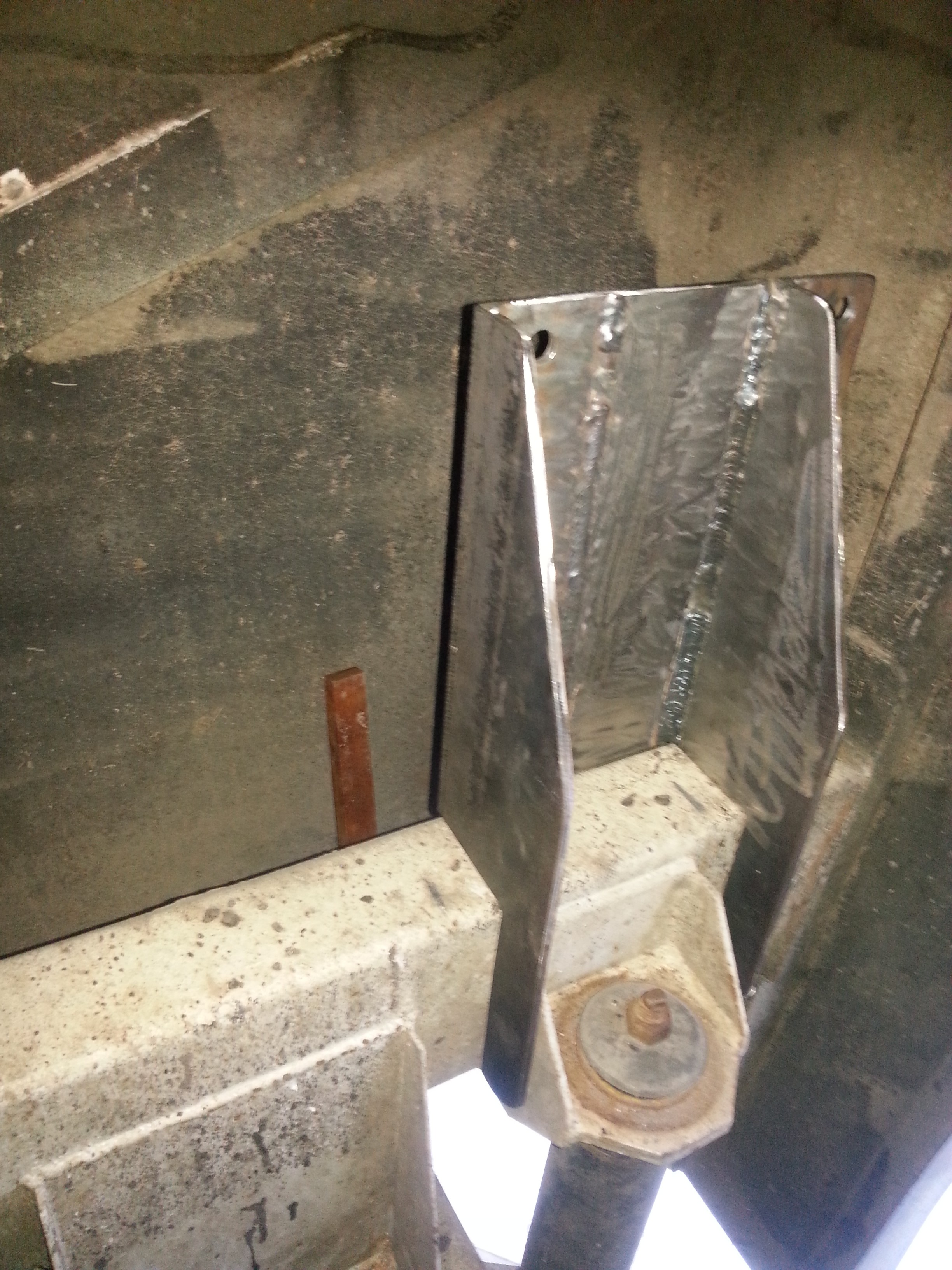
Now that the Electrical drive system is completed for the Rear stabilizers work can proceed to the Leg mountings, these will be constructed from 8mm plate & 100 x 150 x 8mm steel angle. the completed mounts will be welded to the outer ends of the rear suspension Air Bag cross members.

The legs will be bolted behind the cross members in an area which is unimpeded by other equipment. As I am not confident in my vertical welding abilities I will have these mounts welded by a qualified welder, a friend of mine has been very kind in accepting this challenge as the position of the job makes it very hard to access. (Thank you Ken Schoulderman)

The cost of the rear stabilizer system  not counting my time has been very reasonable, Total Cost for Equipment has been just under $1400.00 + (2 cartons of Beer).

Leg bracket to be welded to the rear most suspension beam.

Leg bracket to be welded to the rear most suspension beam.

Passenger side Leg bracket photo 2

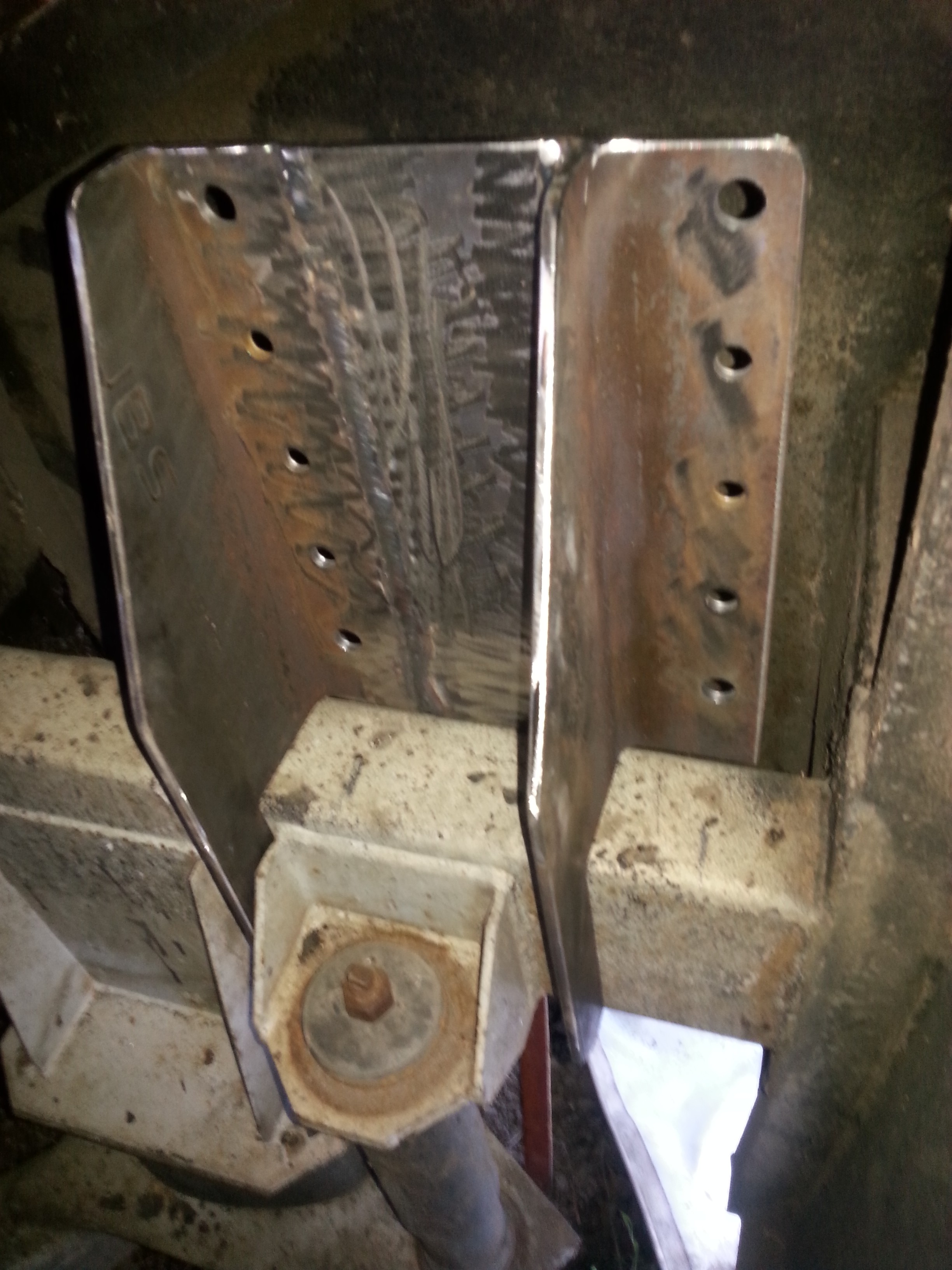
Space between the mount bracket & rear wall of wheel well is very tight, does not look so in photo but there is just enough room for Leg to be bolted behind.

Ready to be welded to beam.

Ready to be welded to beam.

L/H leg mounting bracket

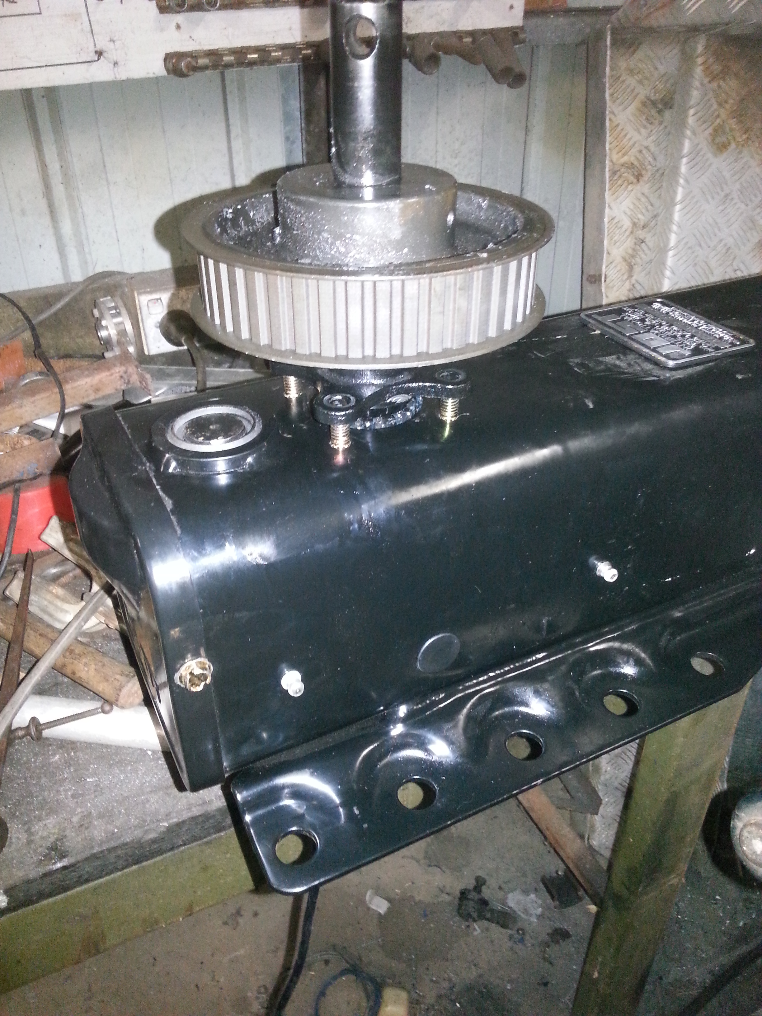
This is the Passenger side unit, it will be welded in place a little closer to the side wall of the RV.

L/H side Leg & Bracket ready for welding to Frame.

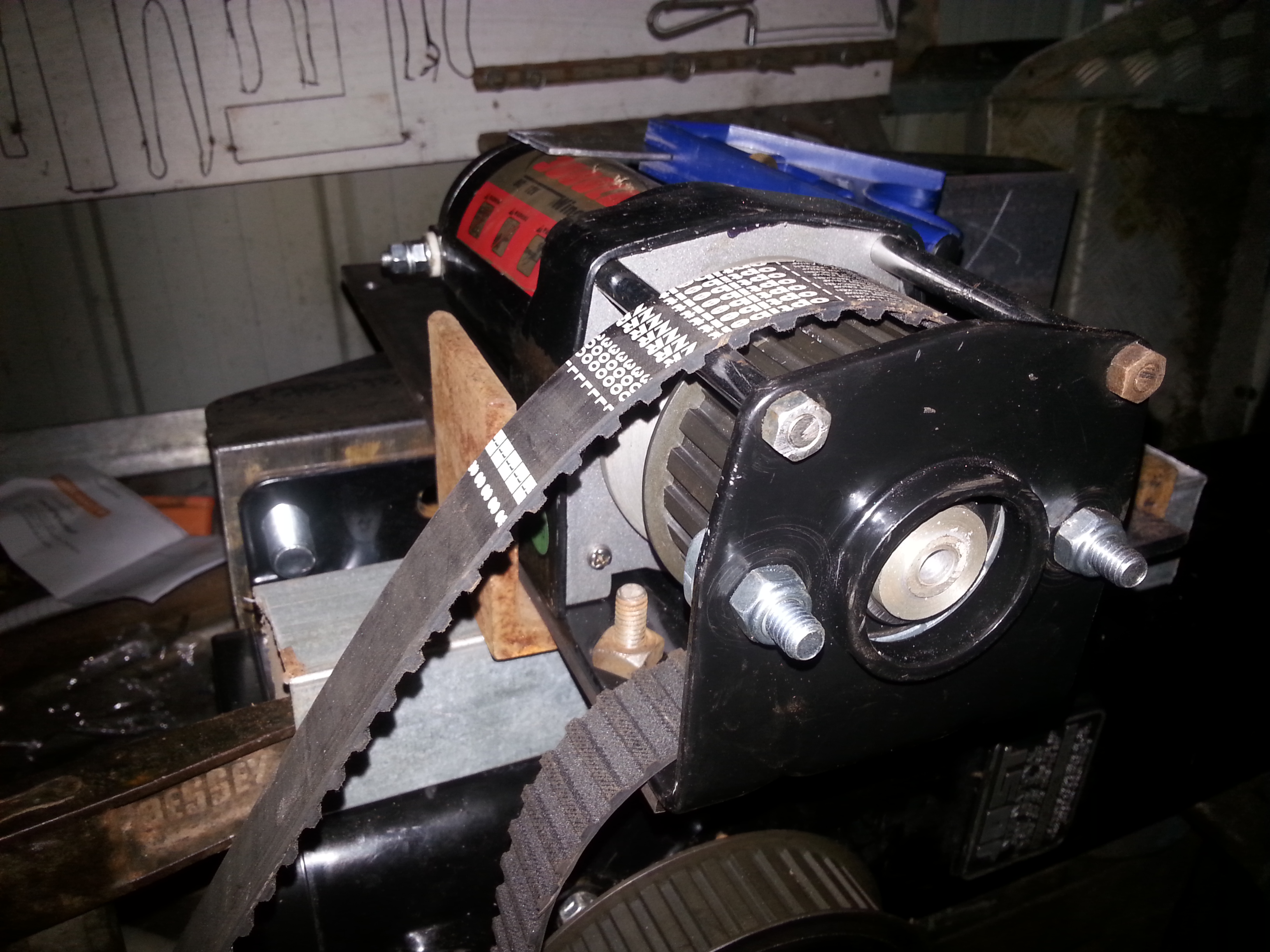
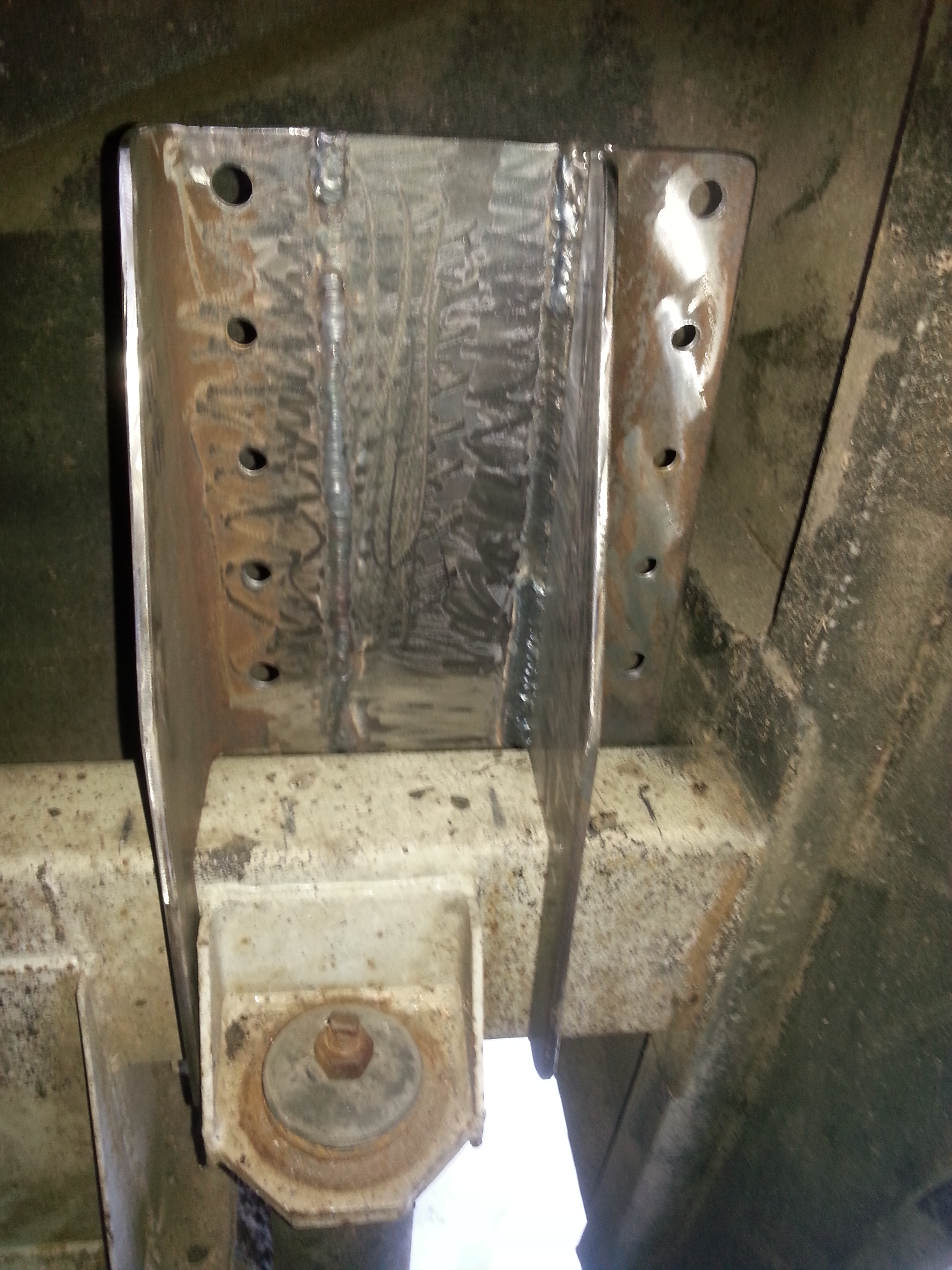
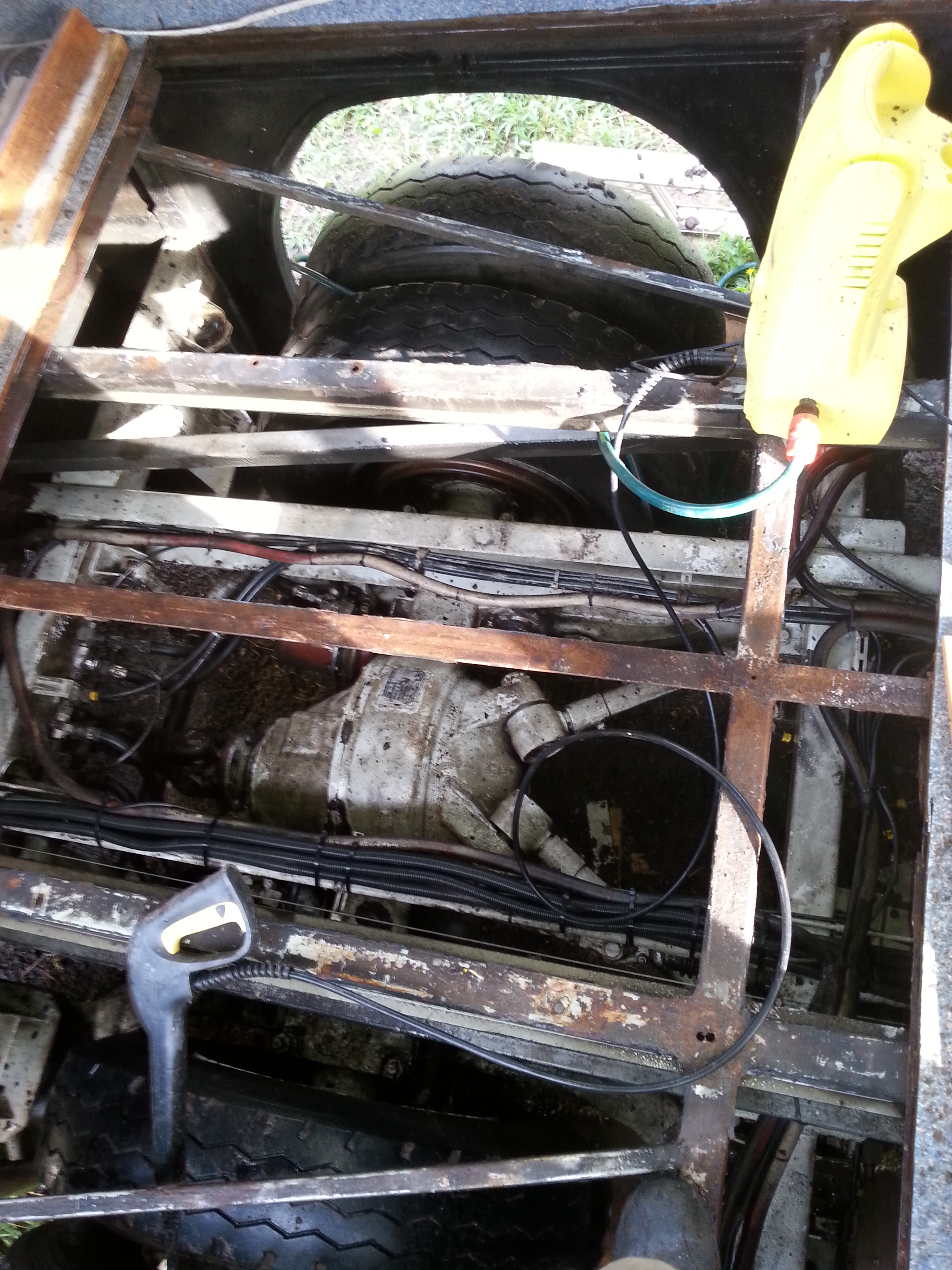
Final mounting position for welding, the small hat section on the left of mount is for mounting the Electrical control unit for the drive motor.

R/H leg mounted on Bracket ready to be Welded to Frame

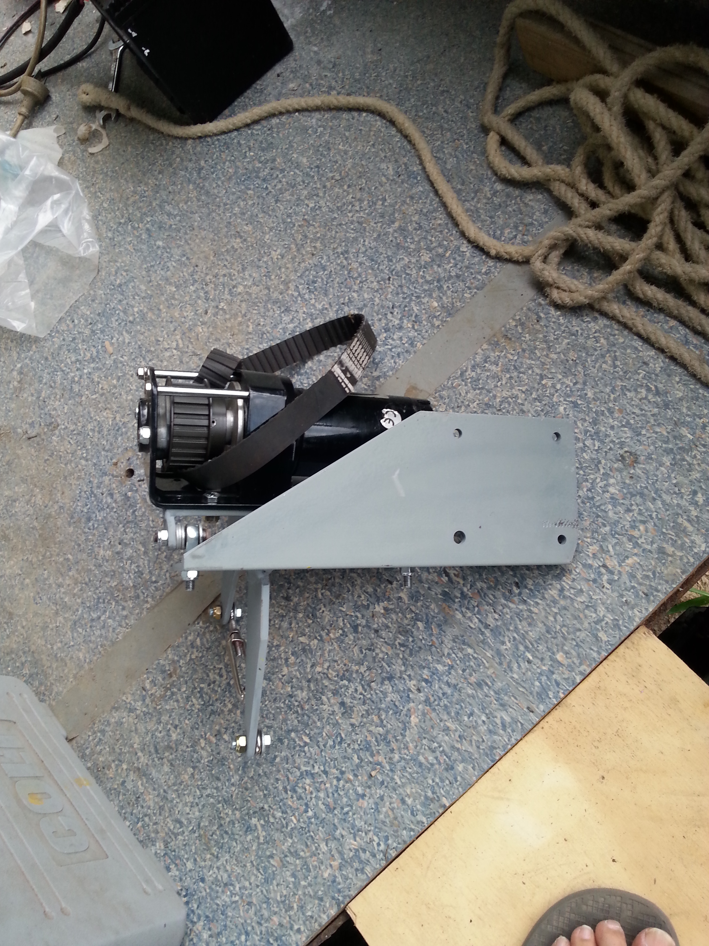
Drivers side mount with leg attached ready to be welded in place.

Floor section removed for work on Shower & Plumbing

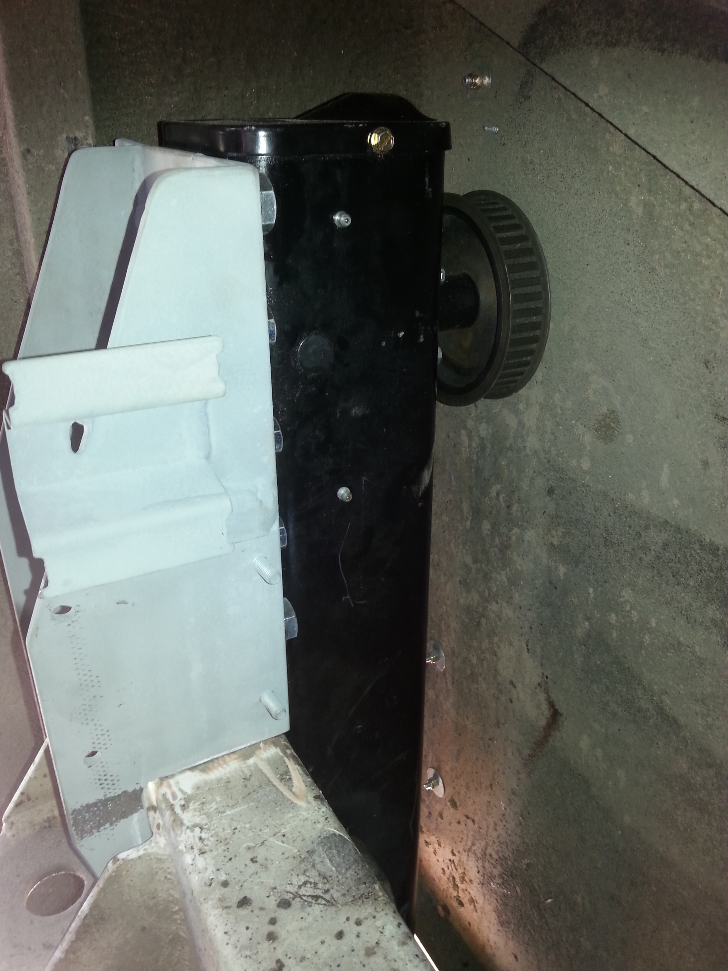
The work on the rear Legs was done while the rear floor had been removed for working on the Shower, Plumbing & Grey water tank.

Rear Stabilizer system overview & drive system.

The Leveling / Stabilizers for the RV ( I am told I can not call it a Bus any longer ) had posed quite a problem for some time as the commercially available units were some what more expensive than I was prepared to pay, I have looked into using individual Hydraulic components & modifying the RV’s Air bag system But both created problems of their own.

I have settled on a Mechanical system utilizing Semi Trailer landing legs, these units have a greater weight lifting capacity & are substantially less expensive once completed.

The ” Jost” Legs selected have a 490mm lift & 25 ton maximum weight. I am driving these units with 12v electric motors which are belt driven on the rear of the RV but chain driven on the front unit.

The drive motors were sourced from 3000lb winch units bought from Ebay, these units cost $86.00 each & come with both Wired & Wireless remote controls.

Pine Rivers bearings were very helpful when sourcing the Pulley & Belt / Chain & sprockets systems.

I will be using 2 stabilizers on the rear of the RV & 1 central unit on the front thus creating a tripod system, this will ensure no torsional stress will be applied to the Chassis when the lift system is used for long periods.

The Electrical system for the drive motors will consist of a Master solenoid to isolate the system, this is controlled from a switch box mounted behind the drivers seat. This houses a master fuse for all power to the lifting legs which are then controlled by separate wireless remotes, there is a facility to use wired controllers if necessary.

Machining the drive pulley to fit the Winch motor arbor.

Machining the drive pulley to fit the Winch motor arbor. Lathe is a 1921 Hercus still going strong.

The winch arbor has been machined to take the driven pulley.

The winch arbor has been machined to take the driven pulley.

Setting the support bearing position prior to fitting the Drive pulley.

Setting the support bearing position prior to fitting the Drive pulley.

Machining completed & Pulley fitted, unit is being set up to make adjusting system for belt tensioning.

Machining completed & Pulley fitted, unit is being set up to make adjusting system for belt tensioning.

The unit is in correct position for mounting, to be rotated 90 deg. Anti-Clockwise & hinged by the lower edge where the belt is feeding out over the lower plate.

The unit is in correct position for mounting, to be rotated 90 deg. Anti-Clockwise & hinged by the lower edge where the belt is feeding out over the lower plate.

The mounting bracket in construction, this part will be bolted to the Leg mounting bracket once welded to the Suspension beam.

The mounting bracket in construction, this part will be bolted to the Leg mounting bracket once welded to the Suspension beam.

Drive sprocket on Leg with shaft ready to be trimmed.

Landing Leg with the Driven pulley mounted, shaft has yet to be shortened.

1 of the 2 drive motors ready to be bolted to the completed leg brackets # 1

Completed drive motor & bracket with adjustment facility.

1 of the 2 drive motors ready to be bolted to the completed leg brackets # 2

Drive unit ready to be fitted to the Leg mount.