The low voltage house power system consists of 4 x 280 Ah Glass mat batteries, these are set up to supply 12v via 2 banks allowing 1 bank to supply power for all the items in use whilst the 2nd bank is being charged from the Solar array. this allows complete charging of the separate banks to ensure a long battery life.
By using 3 separate battery switches this allows greater flexibility of charging & use of the batteries, When the Inverter has AC power whether from the mains or Generator the battery bank currently in supply mode is charged from the Inverter at up to 70amps. When traveling the Vehicle power system will charge this bank at up to 40amps via the Redarc unit.
The battery bank not in use would normally be charged via the 2Kw solar array, when there is plenty of solar power both banks can be coupled for charging & supply power to the inverter for running of the Air Conditioners.
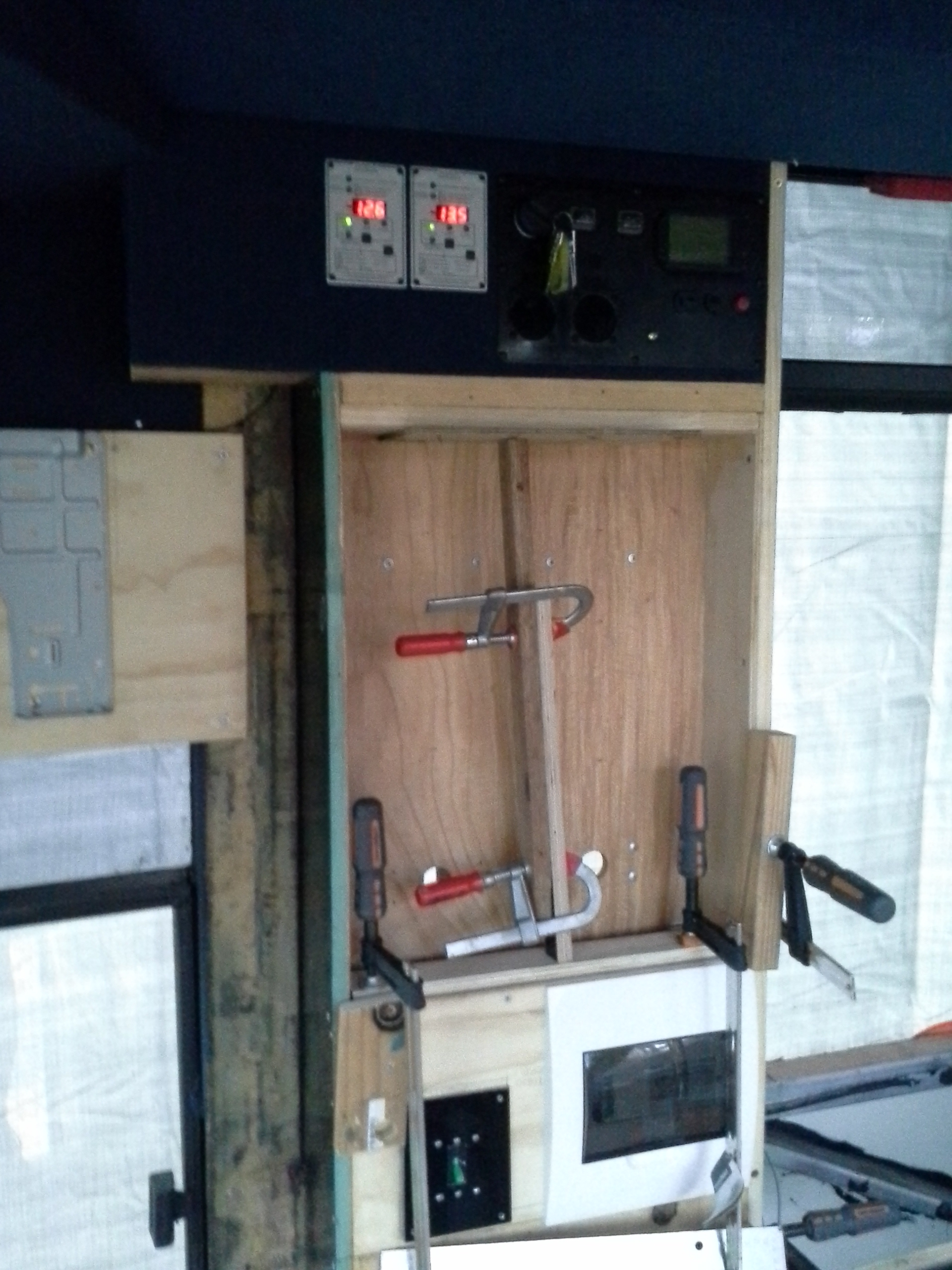
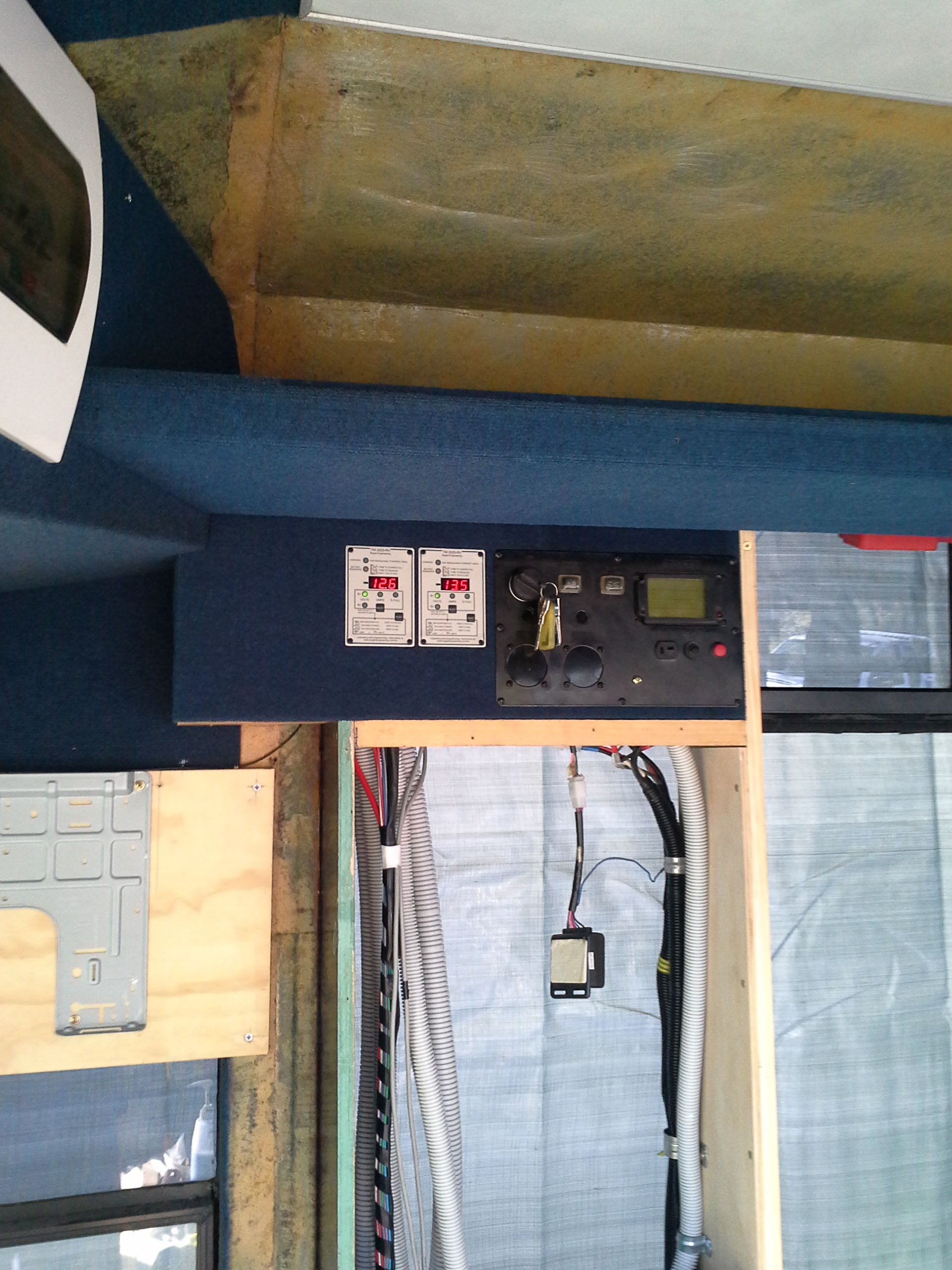
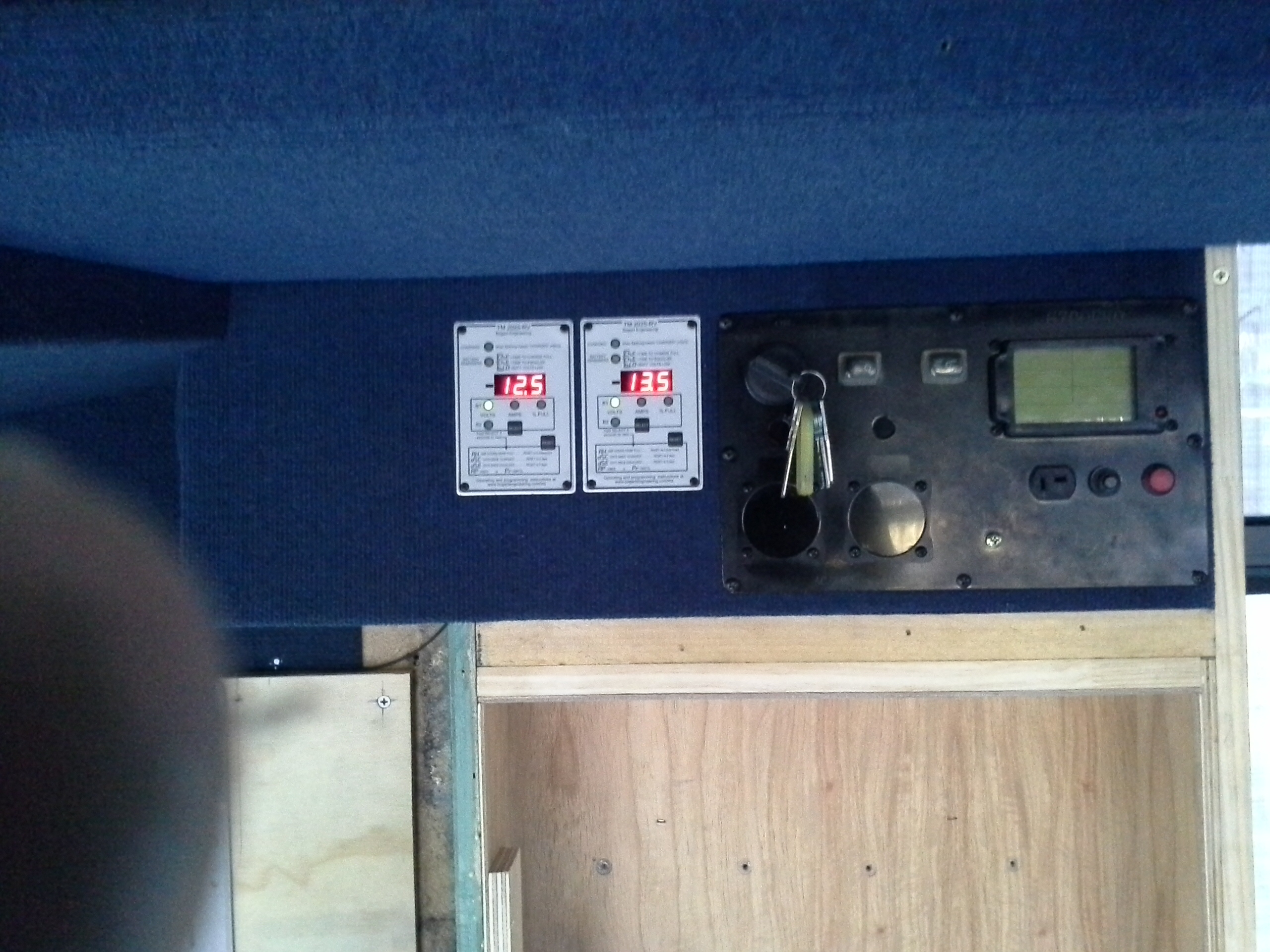
Due to the high power capacity of the Inverter system all main battery leads have been up rated to carry a constant 600amps if needed, this also reduces any voltage drop through the supply system due to the distance the 12v system is required to supply from. Both banks have 500amp shunts on the earth side & battery monitors to allow control over the depth of discharge to ensure good life expectancy.
All lighting, the 3 Fridges, Toilet, Diesel hot water control, Water pumps, Radio, TVs & Vast Satellite system are run from the 12v system. When the Solar system is not available due to weather I can use the Diesel generator to power the Inverter for recharging the system.

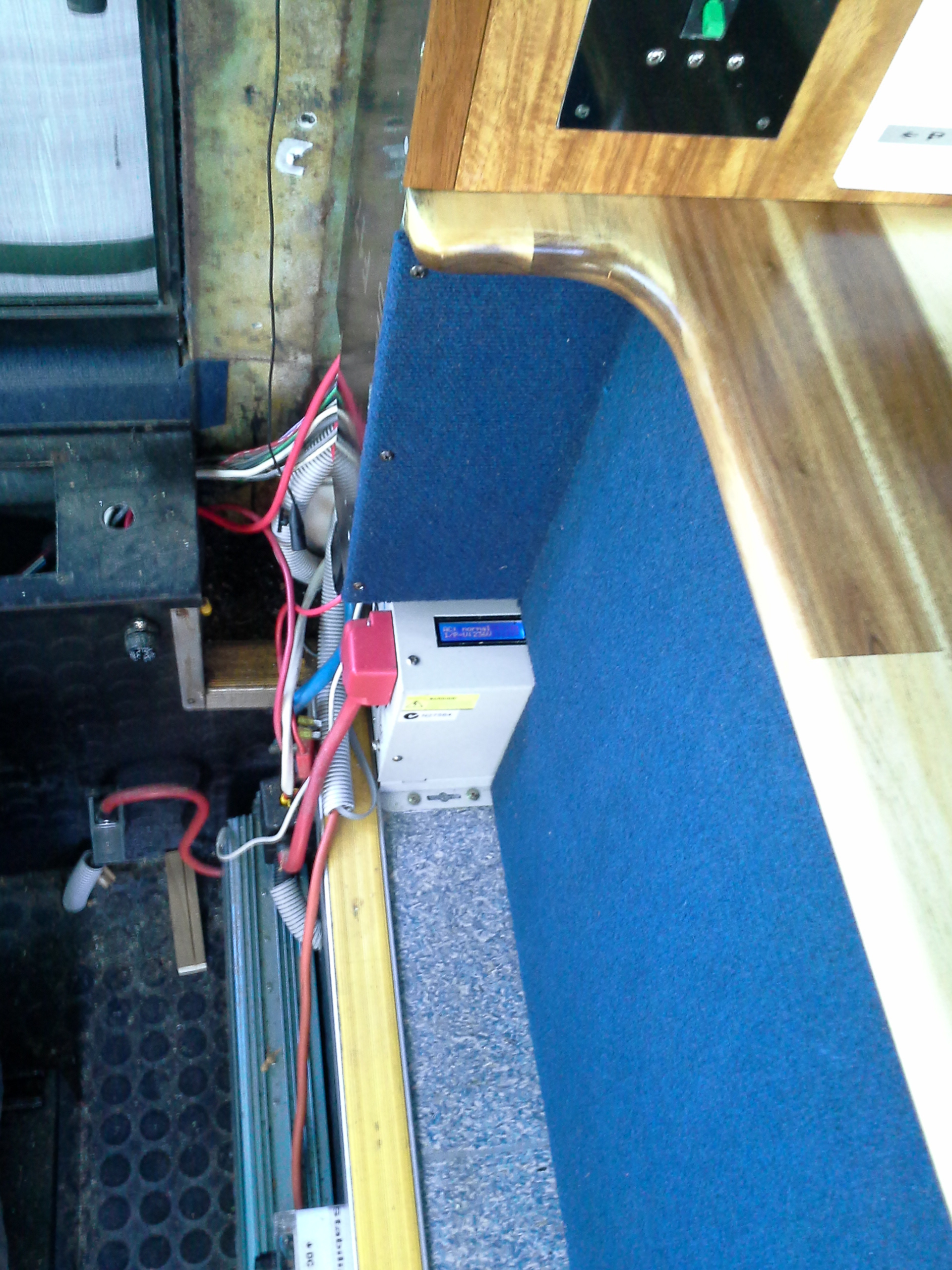
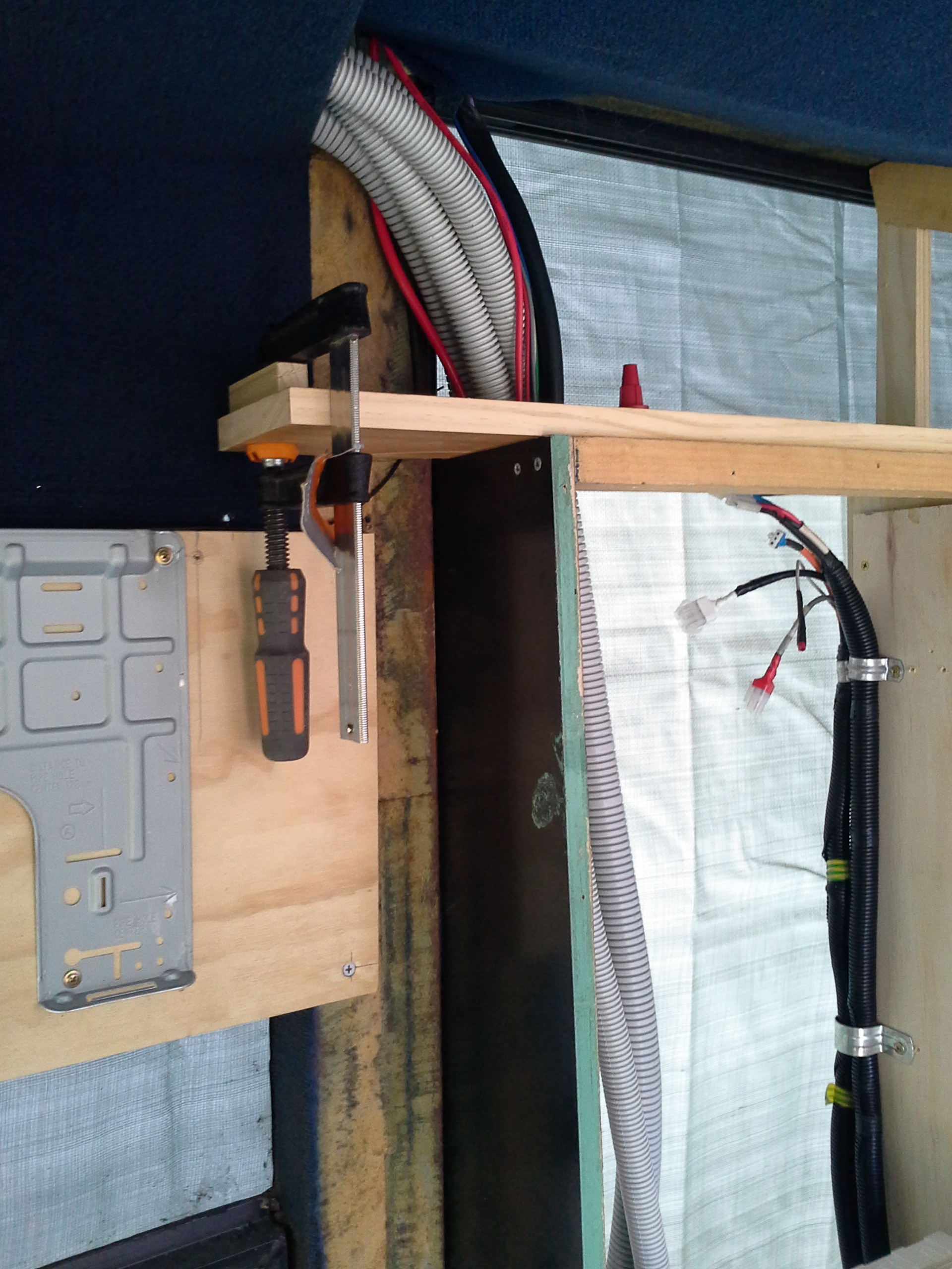
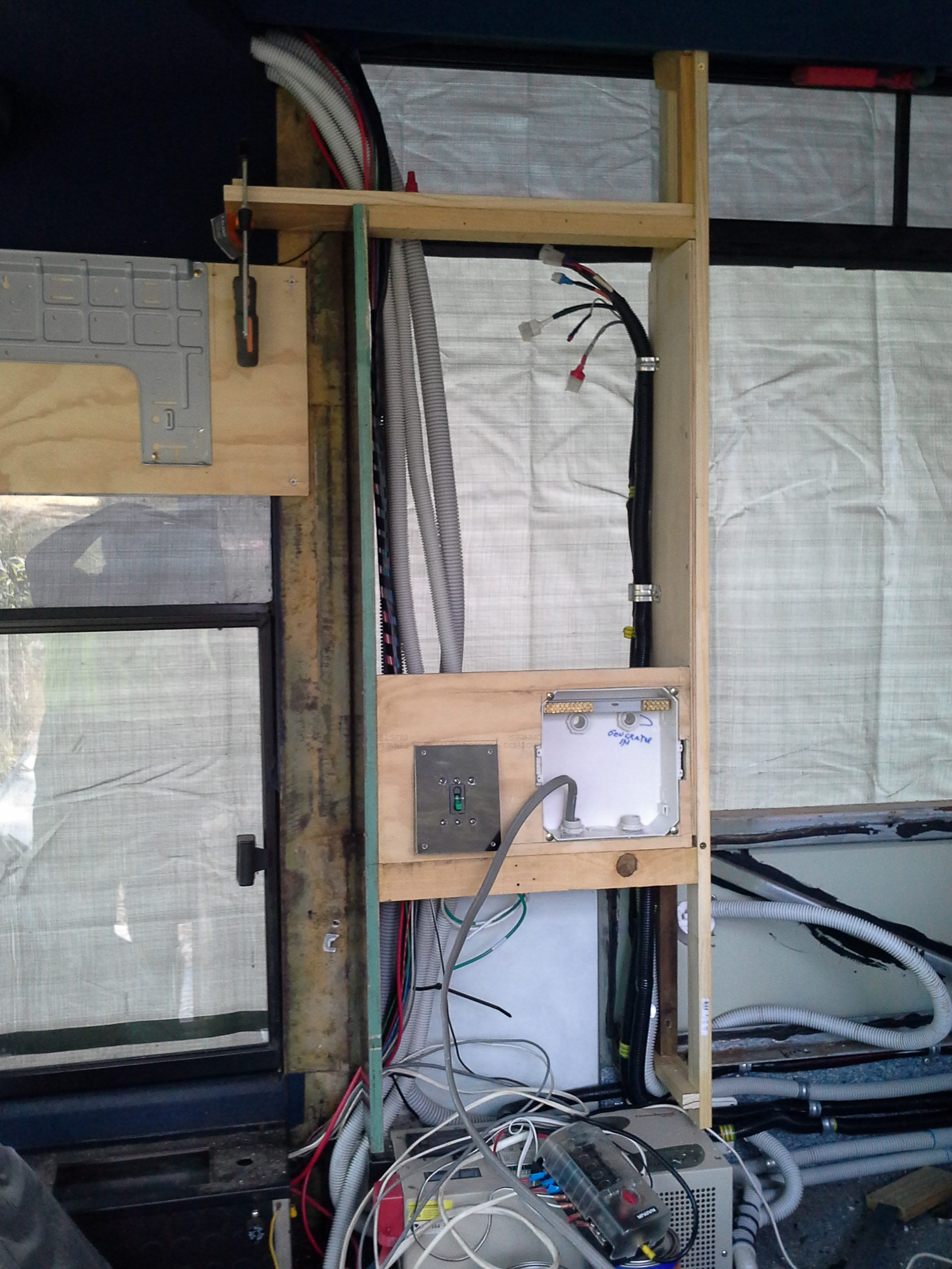
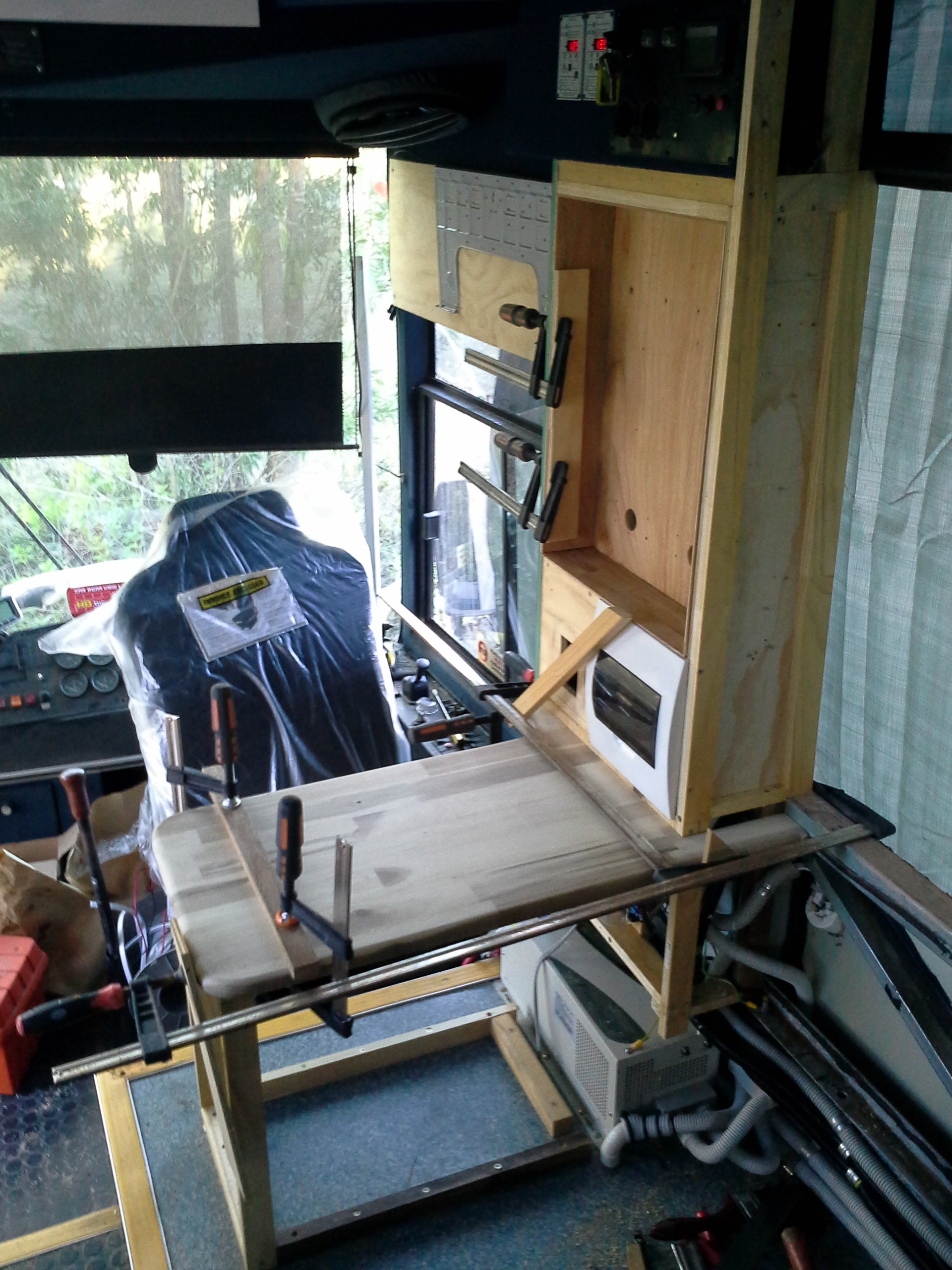
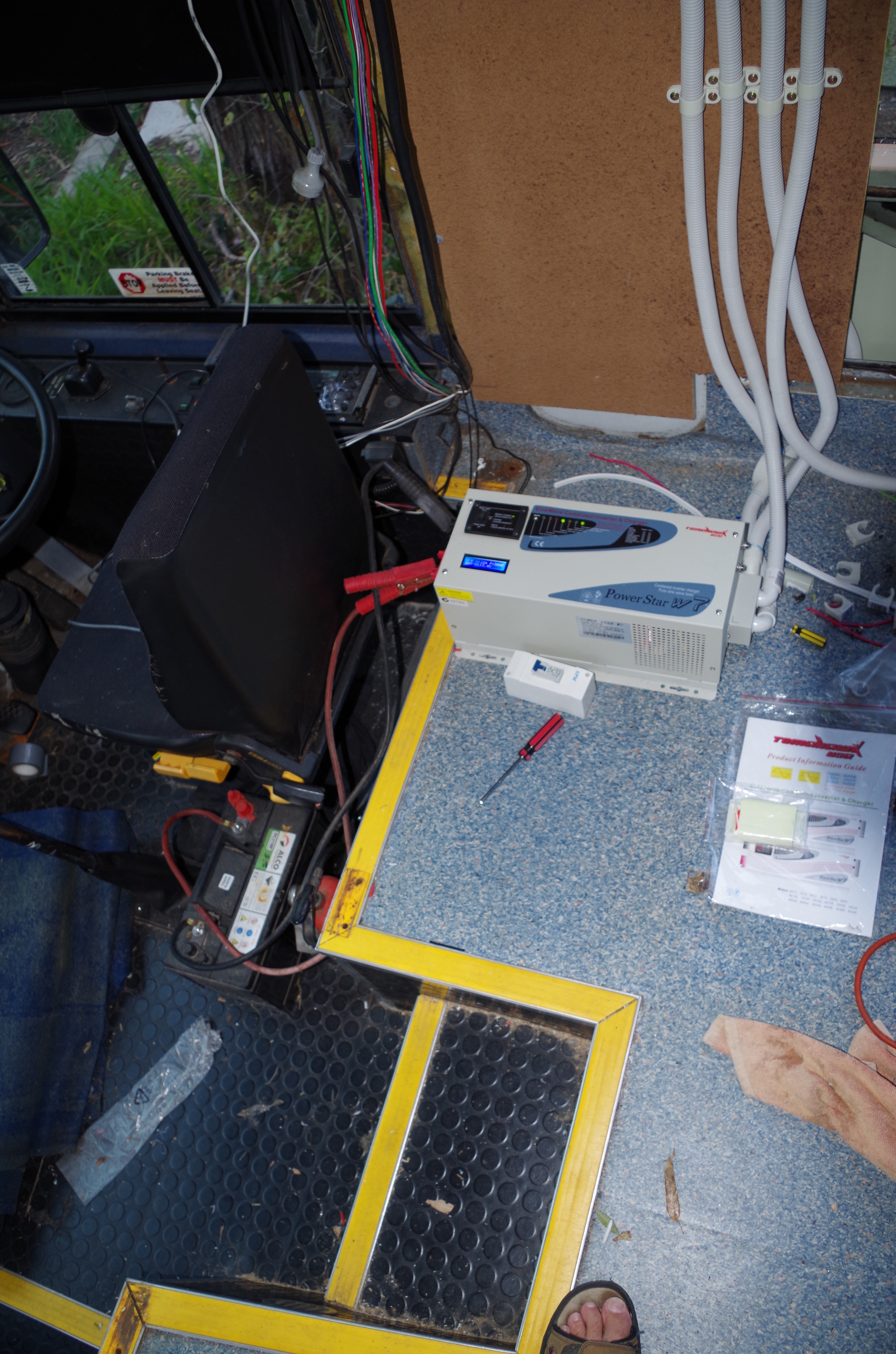
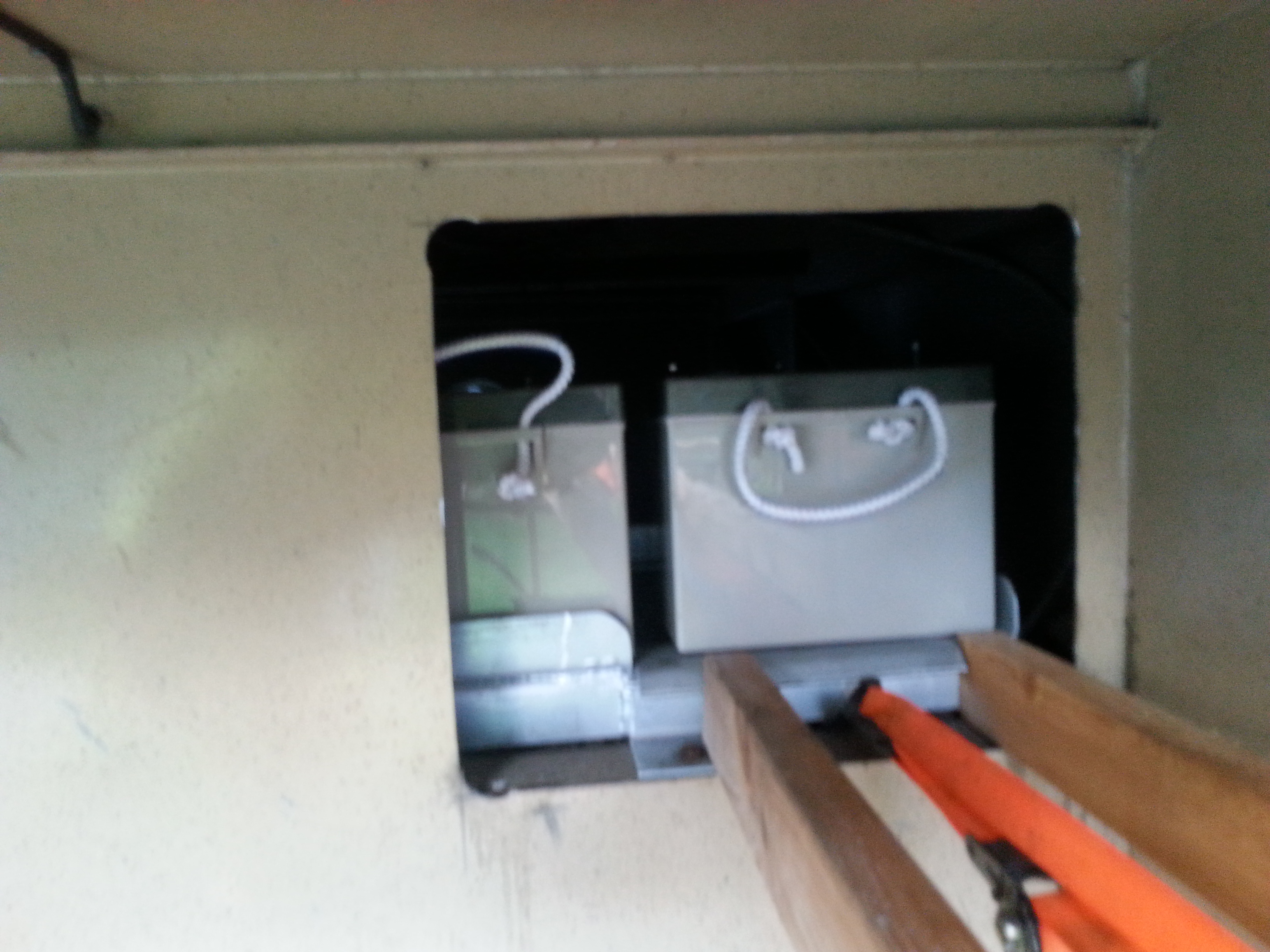
The Inverter in its temporary position prior to the low voltage system installation, the battery switches are mounted immediately behind the driving position on the low wall to the left on the approach to the steps.

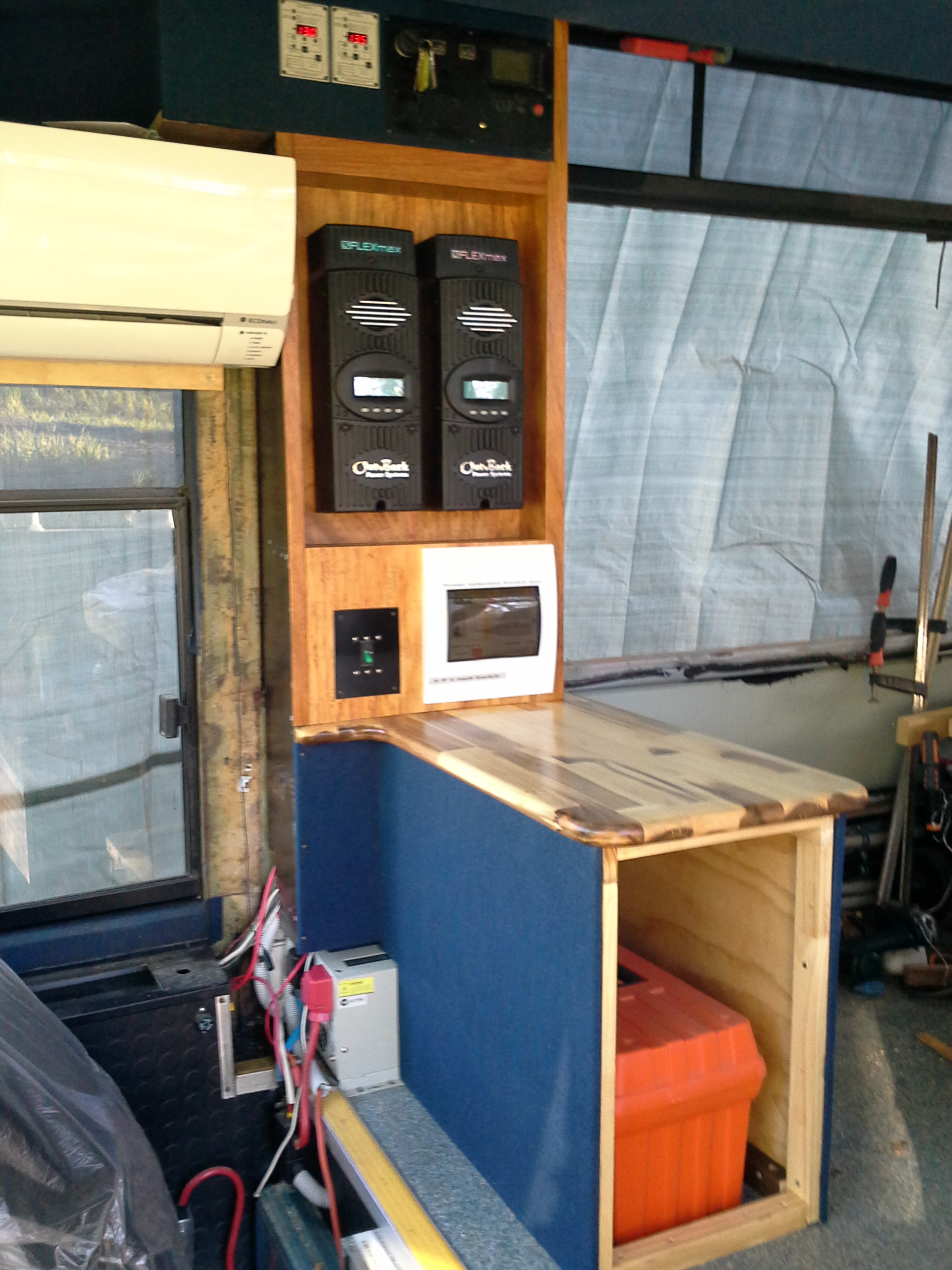
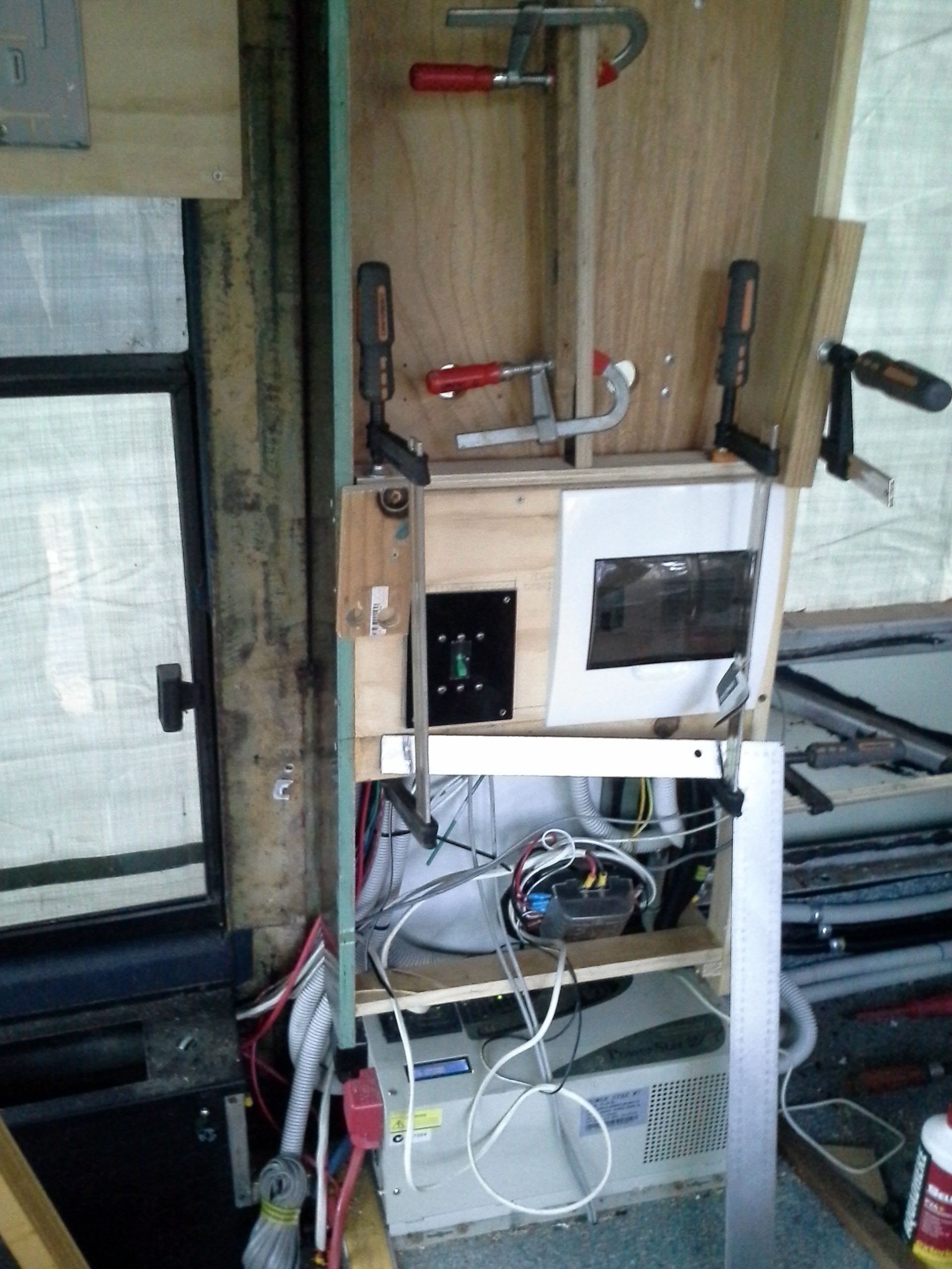
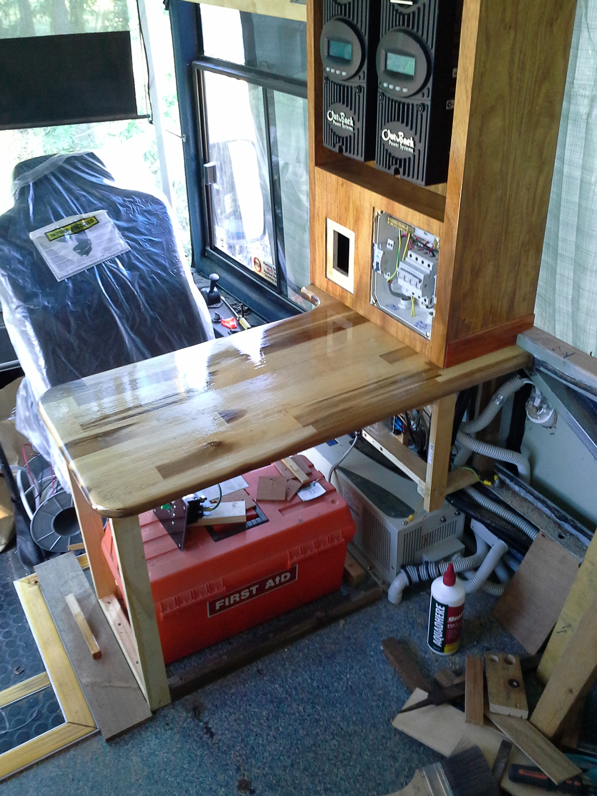
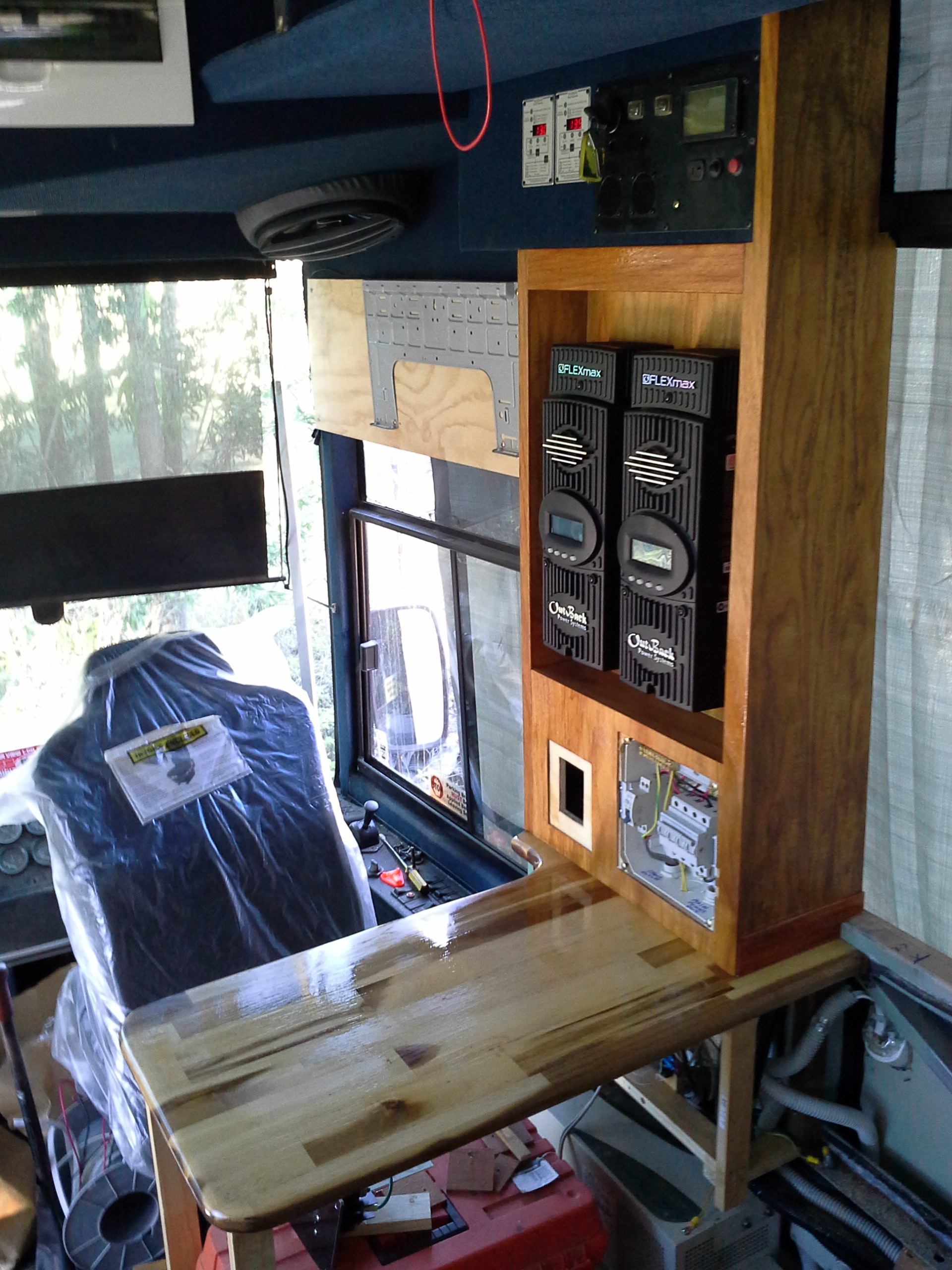
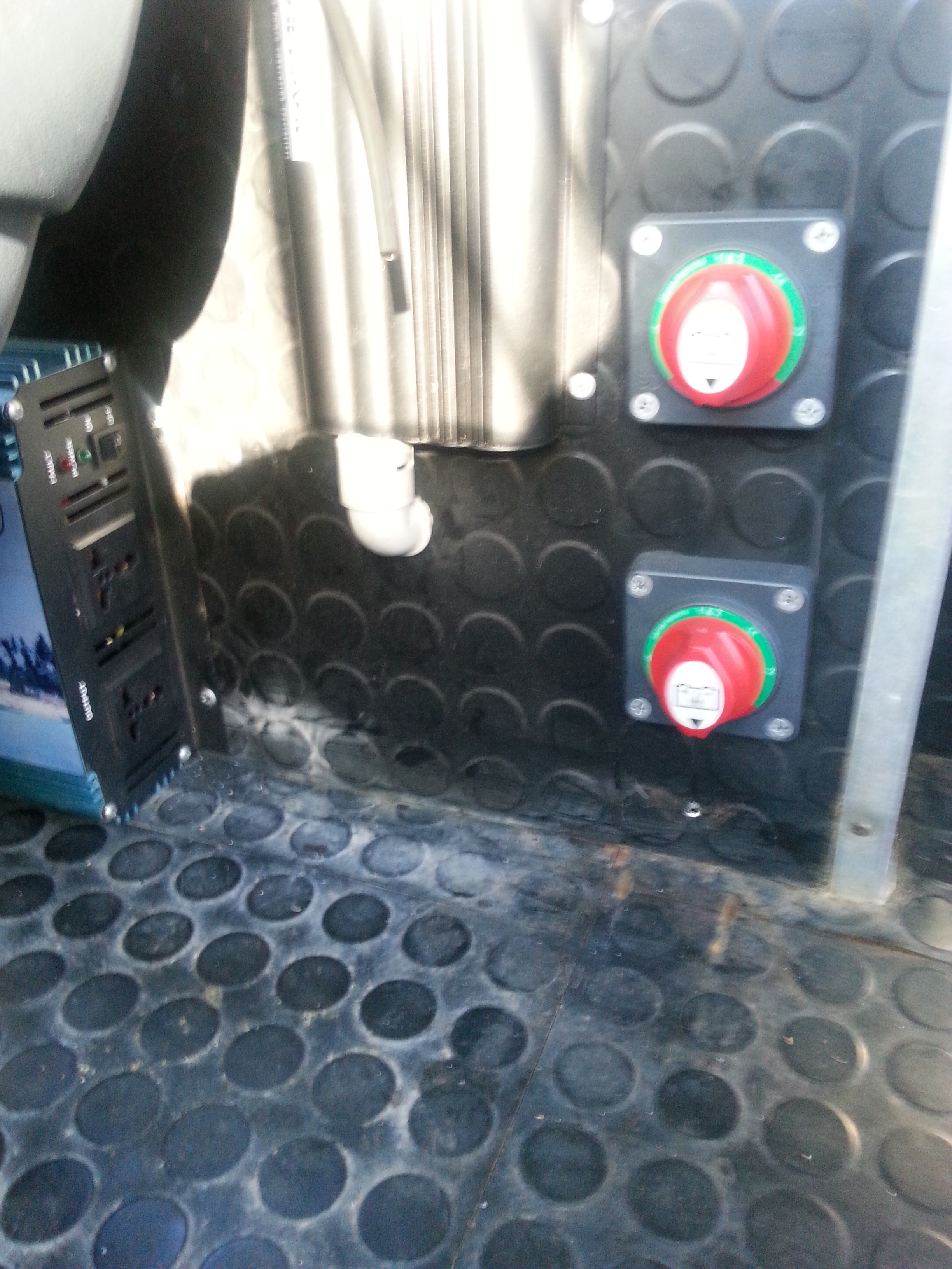
The selection switches for the Battery banks, (front & rear) these switches allow for selection of battery banks to individually supply power, receive charge from the Solar array or be coupled together as 1 bank. the item to the left of the upper switch is a Redarc 1240dc-dc charge controller which will supply charge to the bank currently in use when the Vehicle engine is running.

The Inverter/Charger unit, this unit has a peak power output of 7000w & 70 amp charging mode.