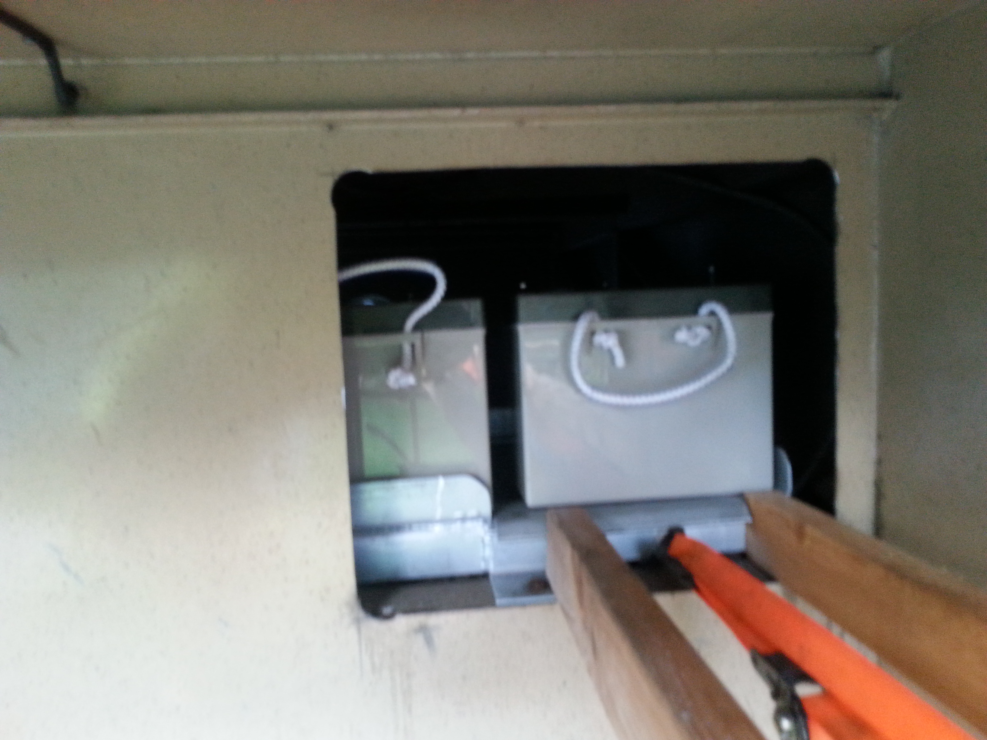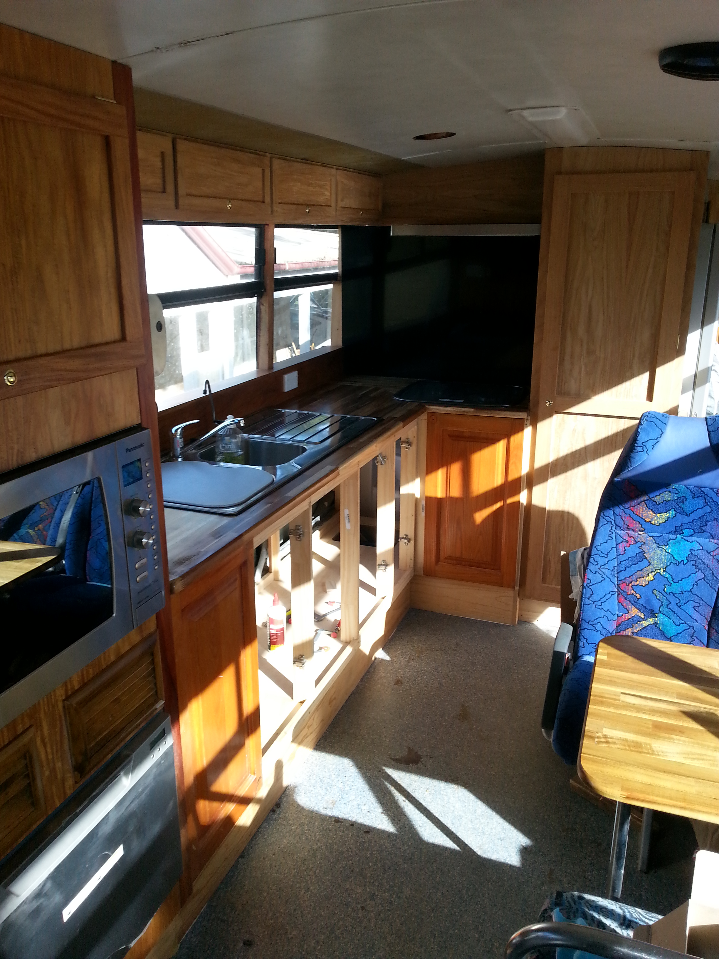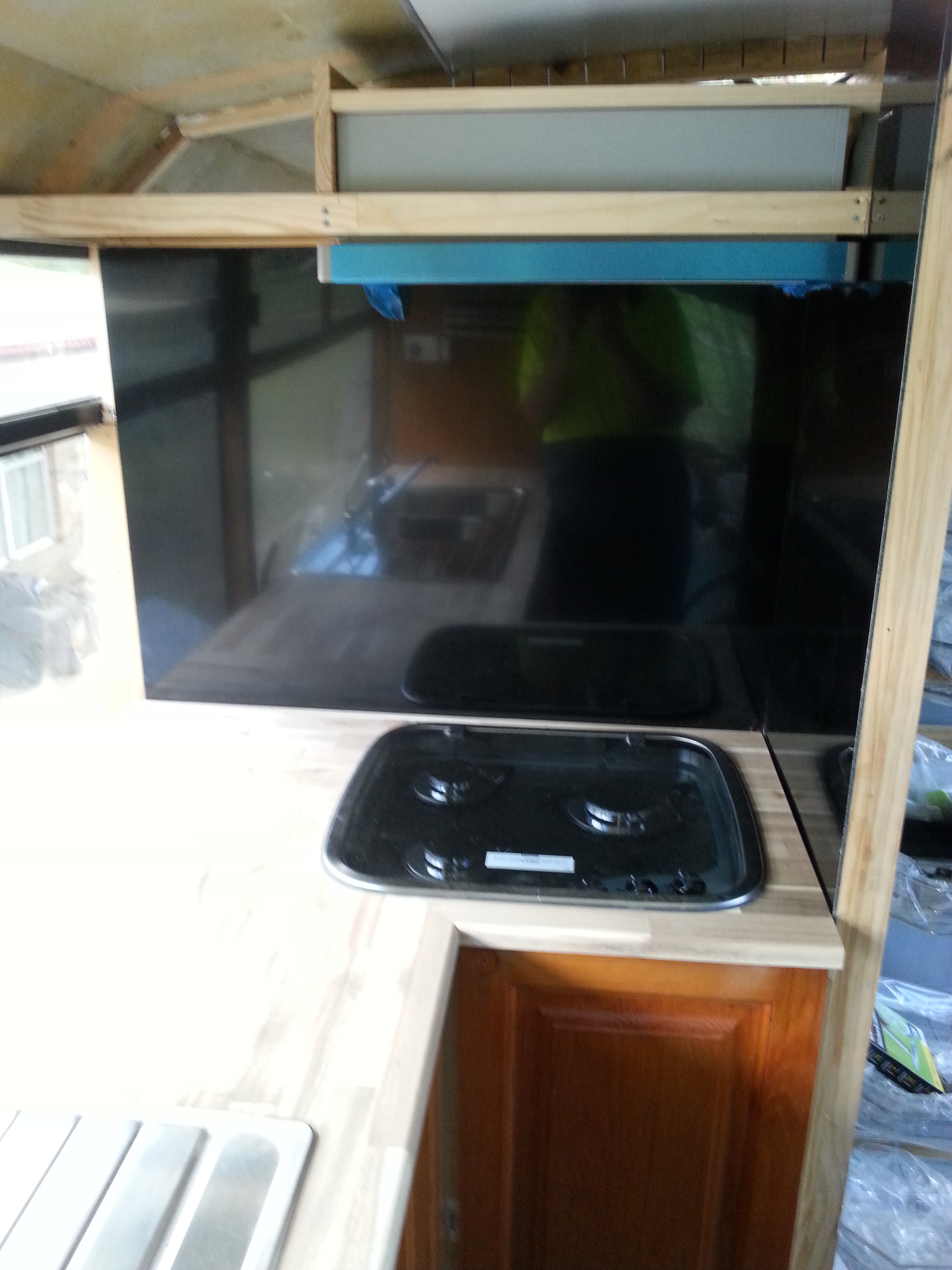
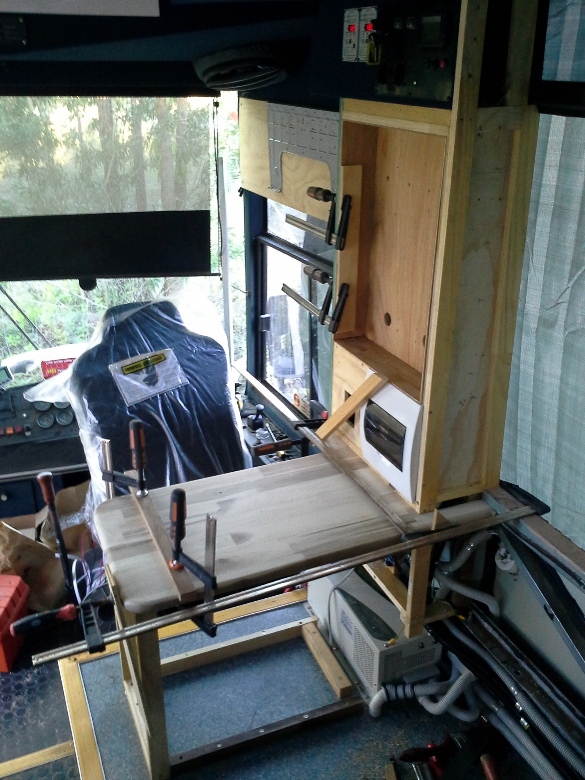
Cabinet frame has been completed & sheeting has been applied.
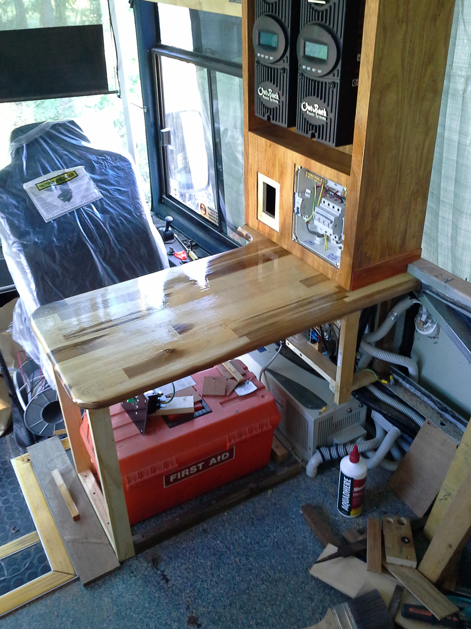
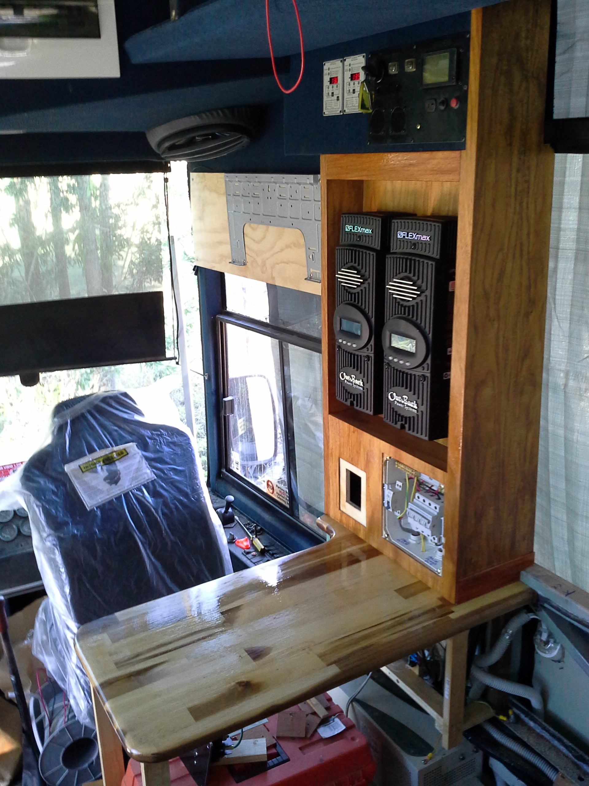
The Solar Controllers have been fitted but yet to be wired, the storage area for the first aid kit & the HID torch is under the bench but this is yet to be sheeted & the door made.
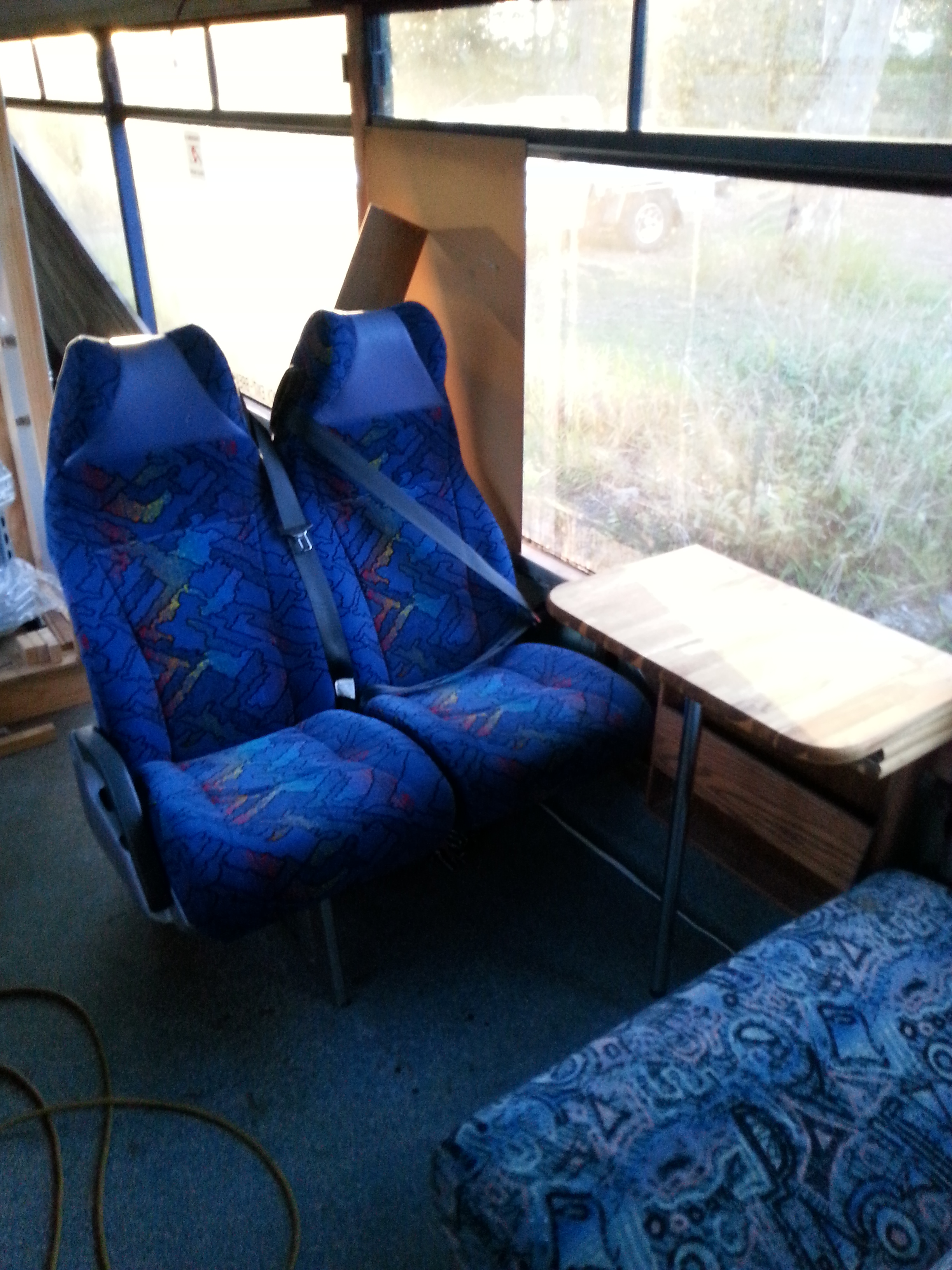
The bench forms a coffee table for the front end of the lounge & the wall of the cupboard behind the drivers seat will be used to mount one of the 2 fire extinguishers for the inside of the RV.
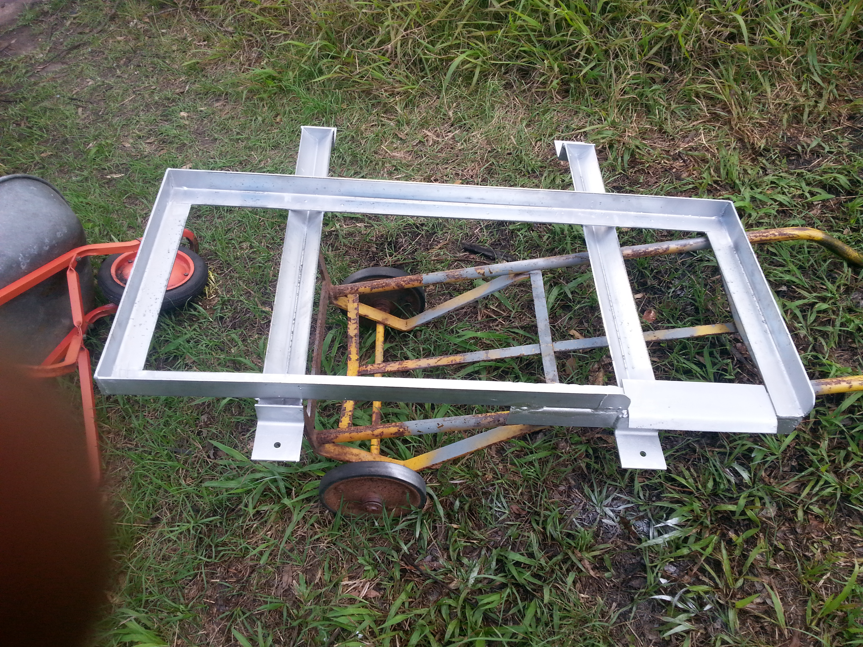
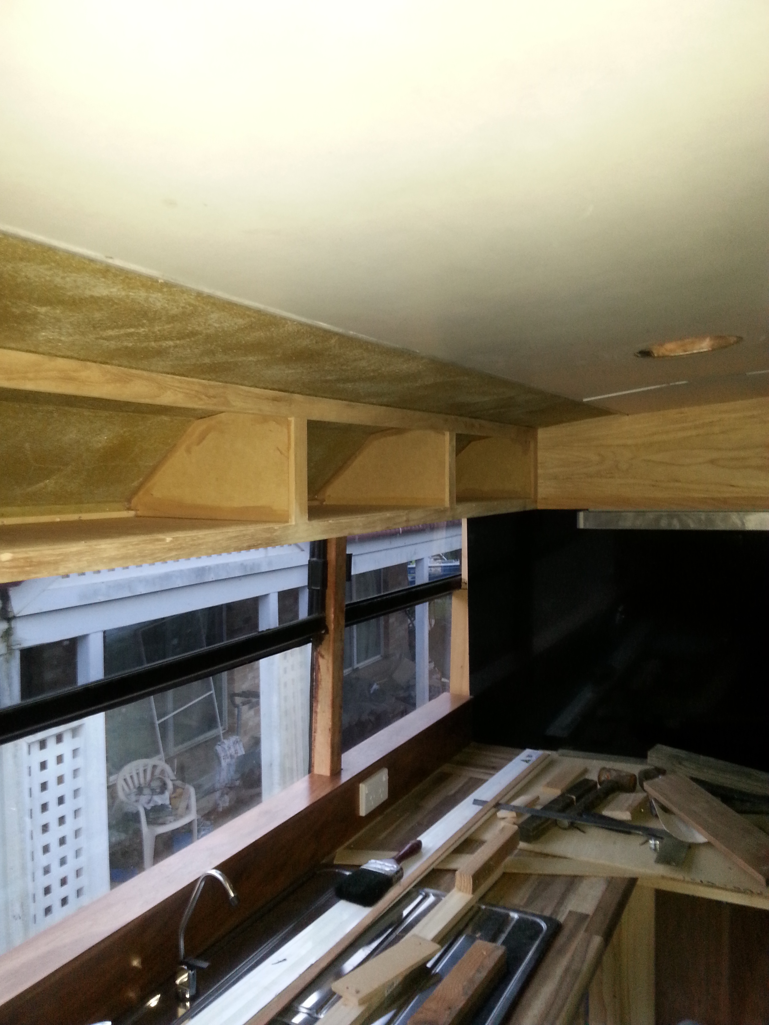
Start of the cabinet construction.

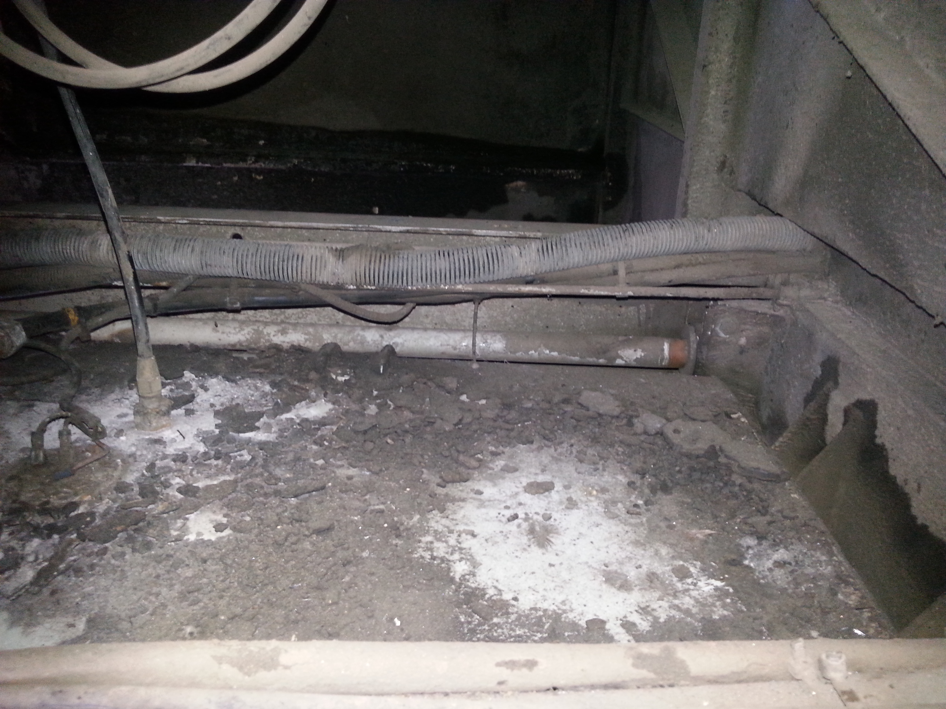
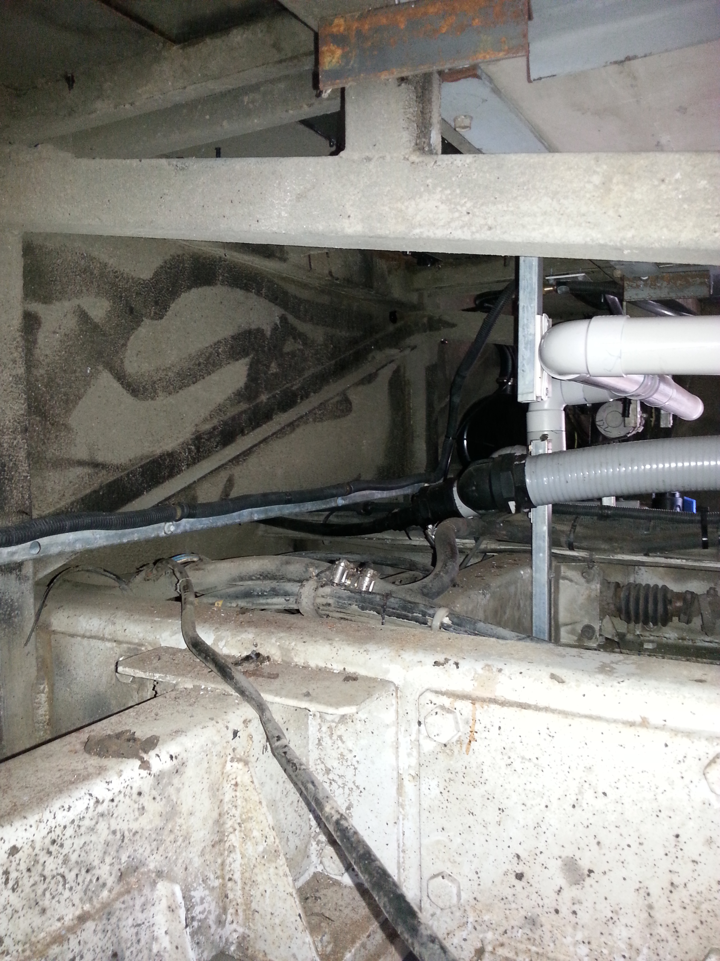
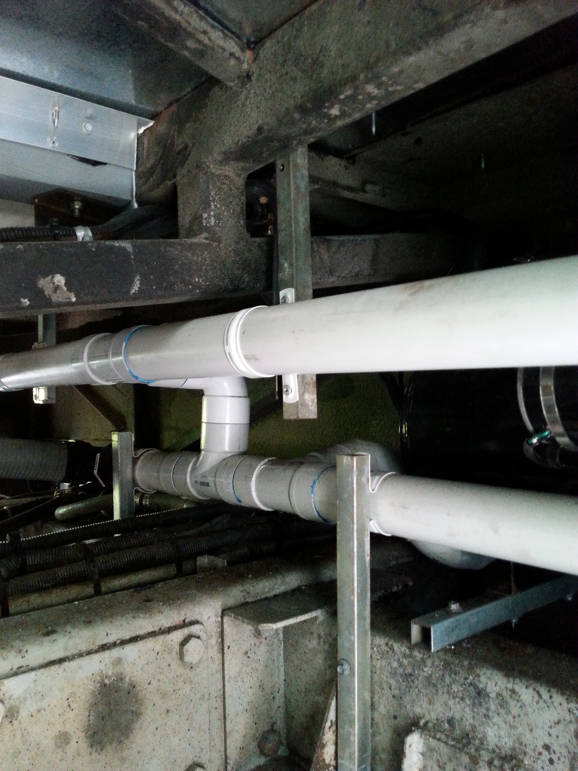
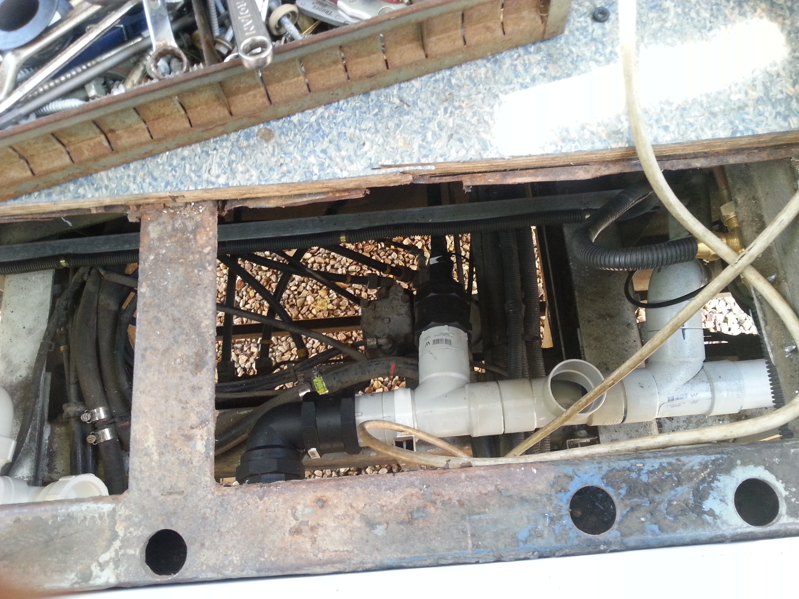
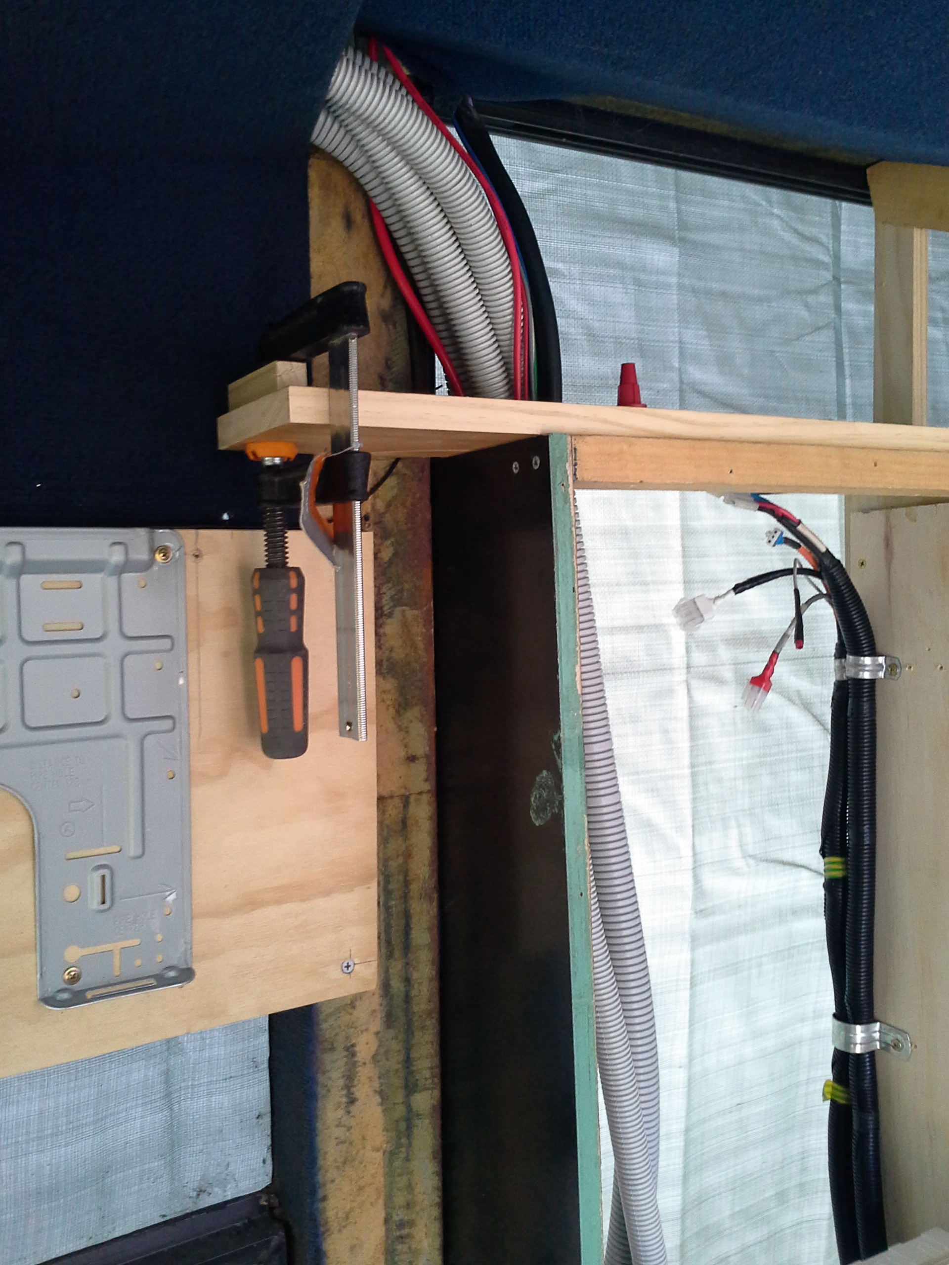
All of the grey conduit running through the back of the Electrical control cabinet are either 240v AC power into or returning from the Mains Safety box mounted over the Driver.
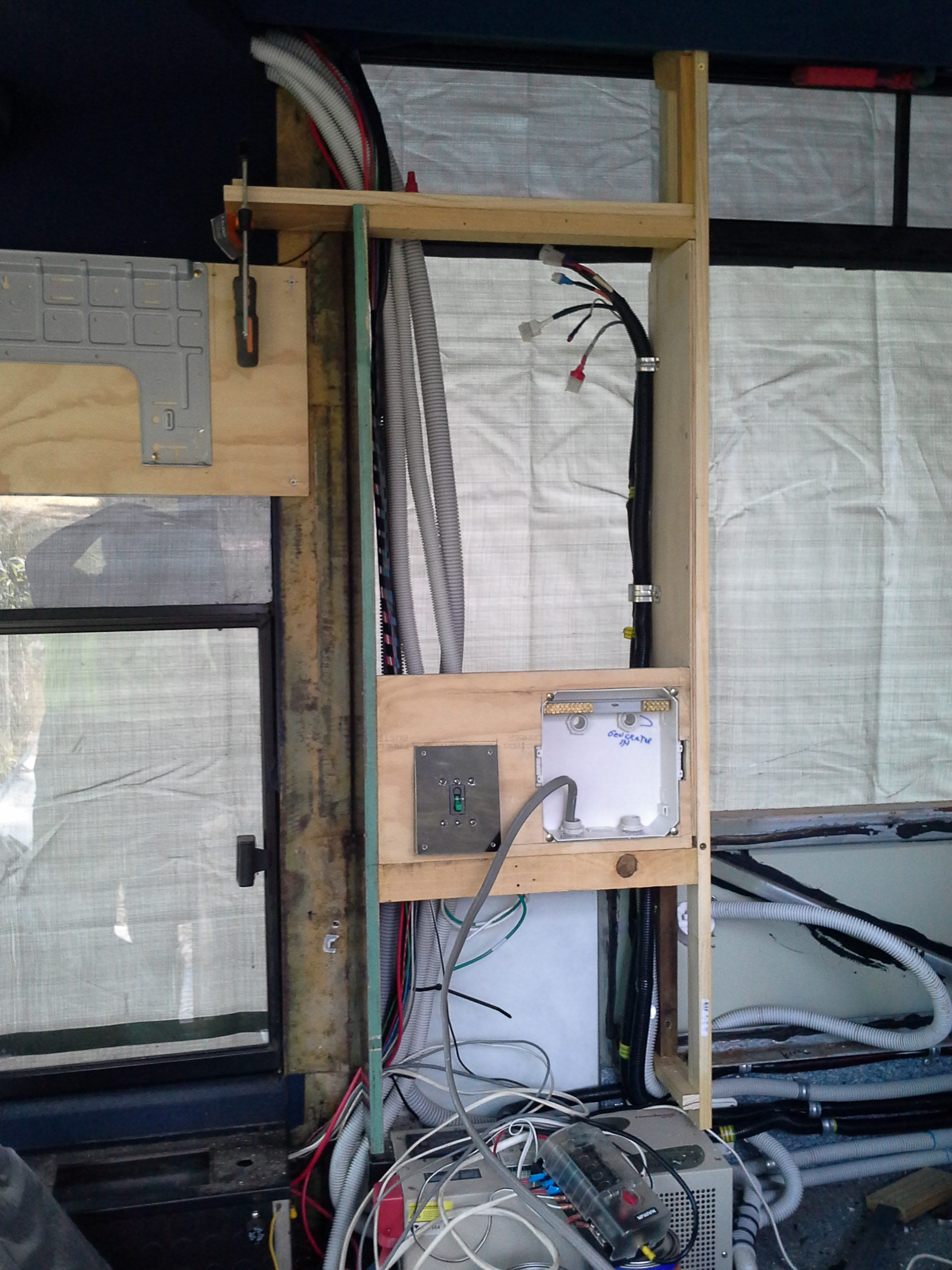
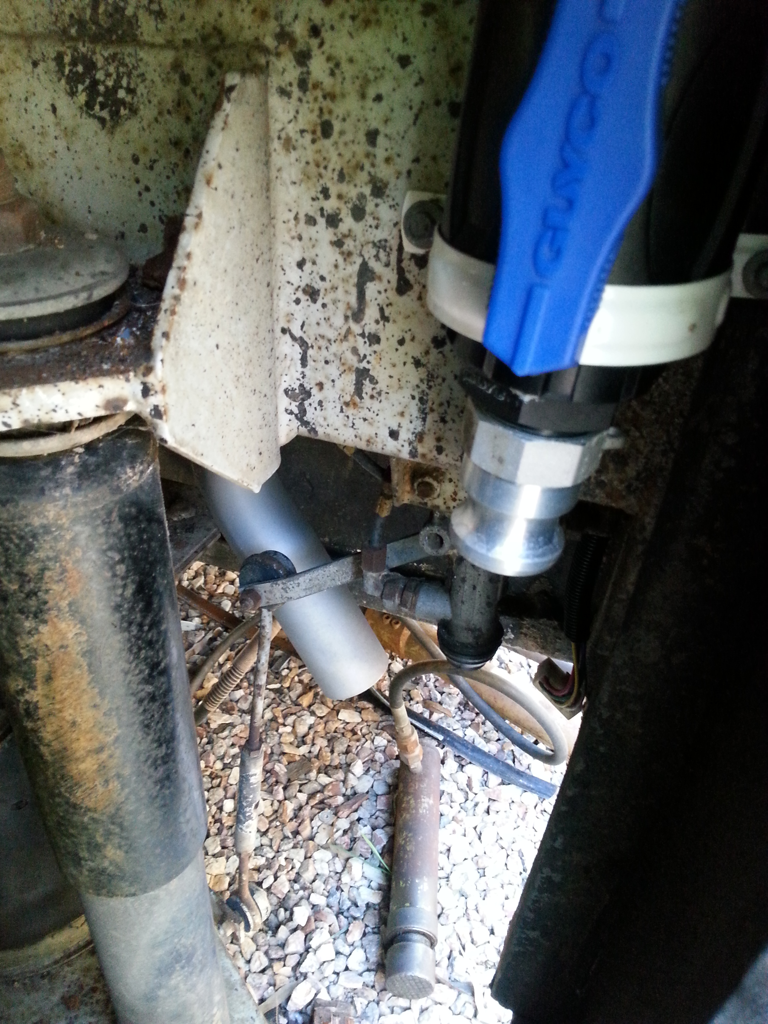
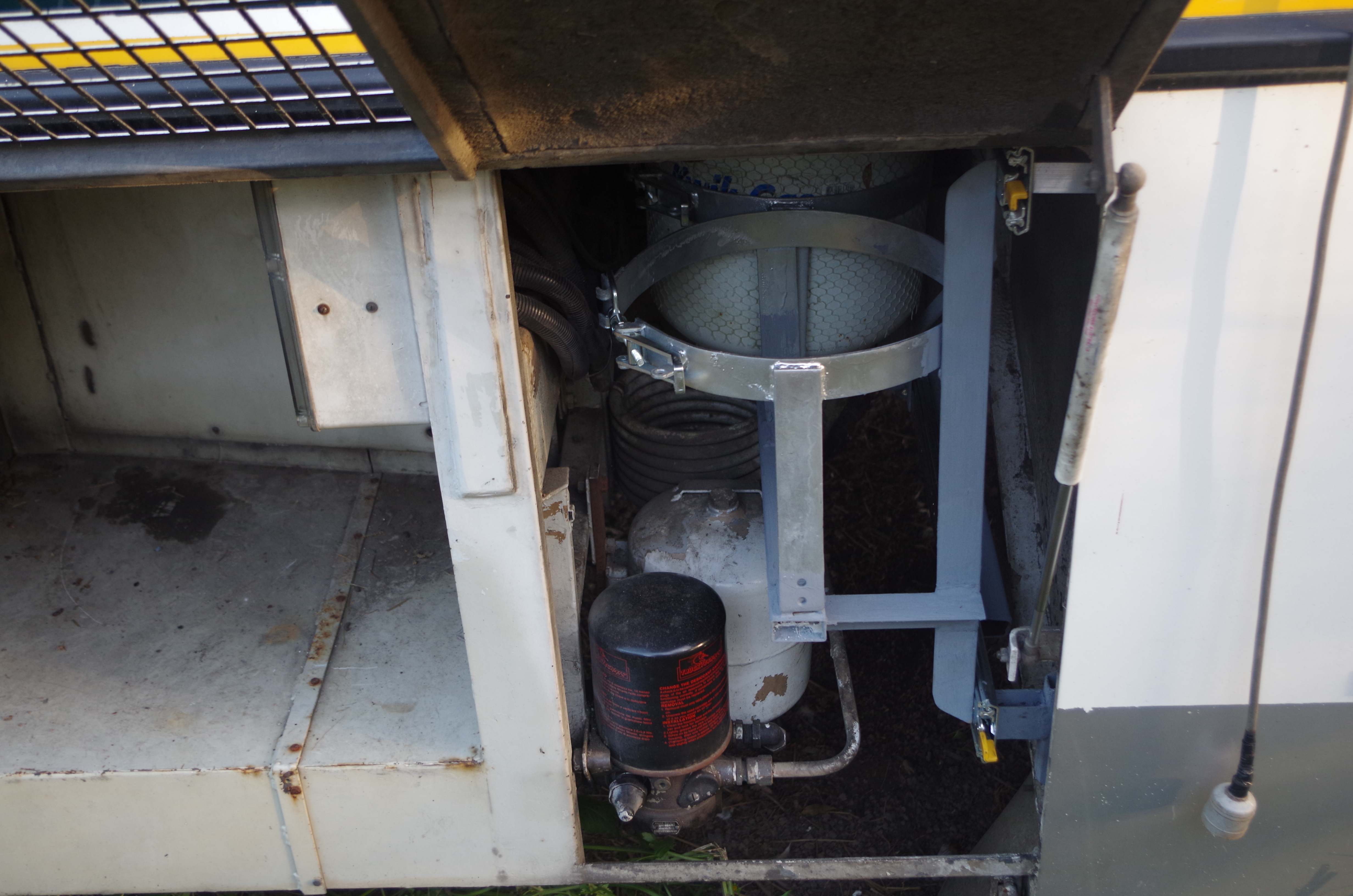
The Black conduits running up the R/H side are the remote control cabling for the Generator mounted in the Forward most R/Hand storage Bin.

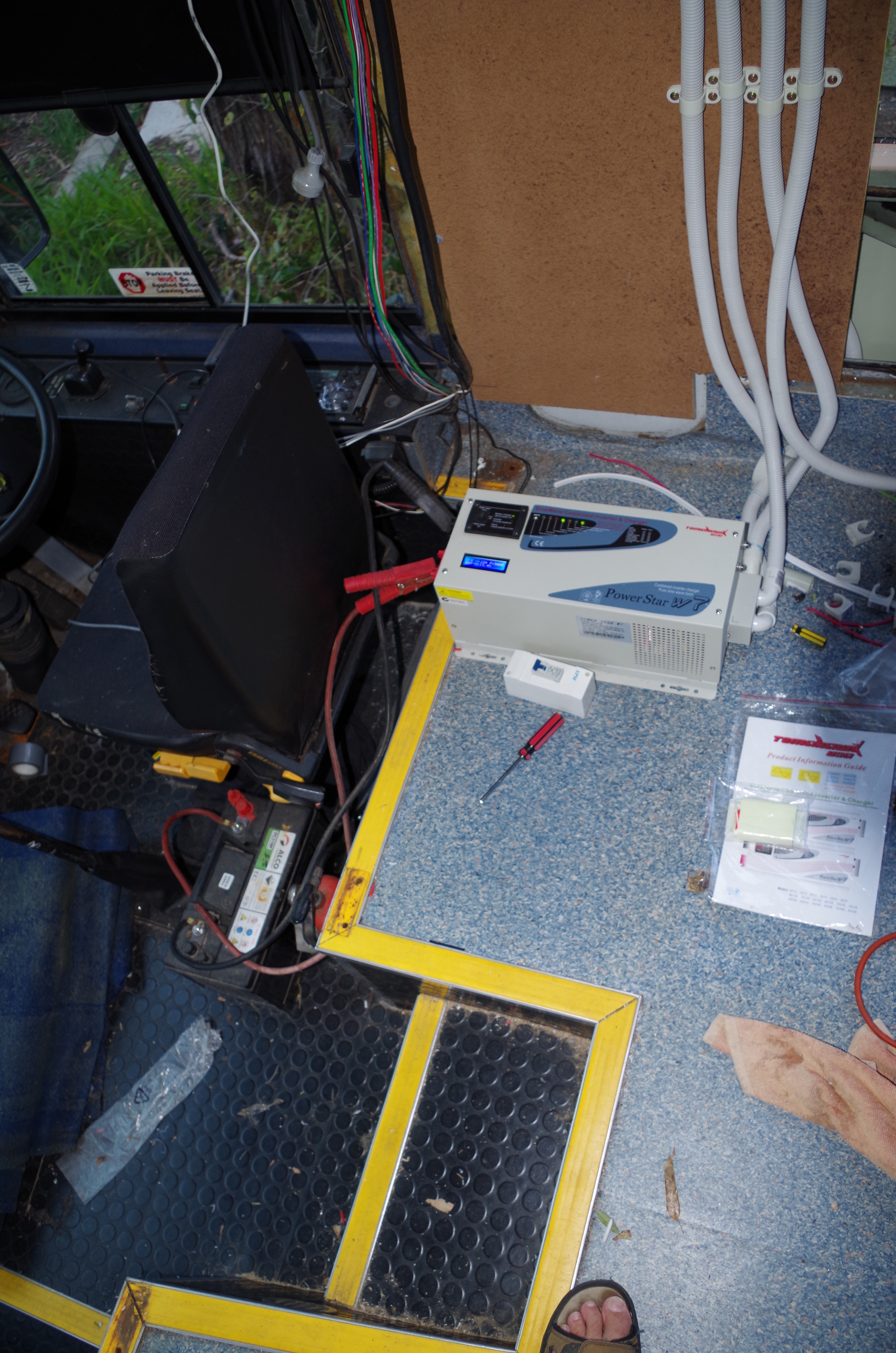
The Power box on the right will house the Selector switch to allow the power source to be chosen from the Mains or on-board generator, It also will contain a safety switch for the 15amp circuit for welding directly from the Generator.
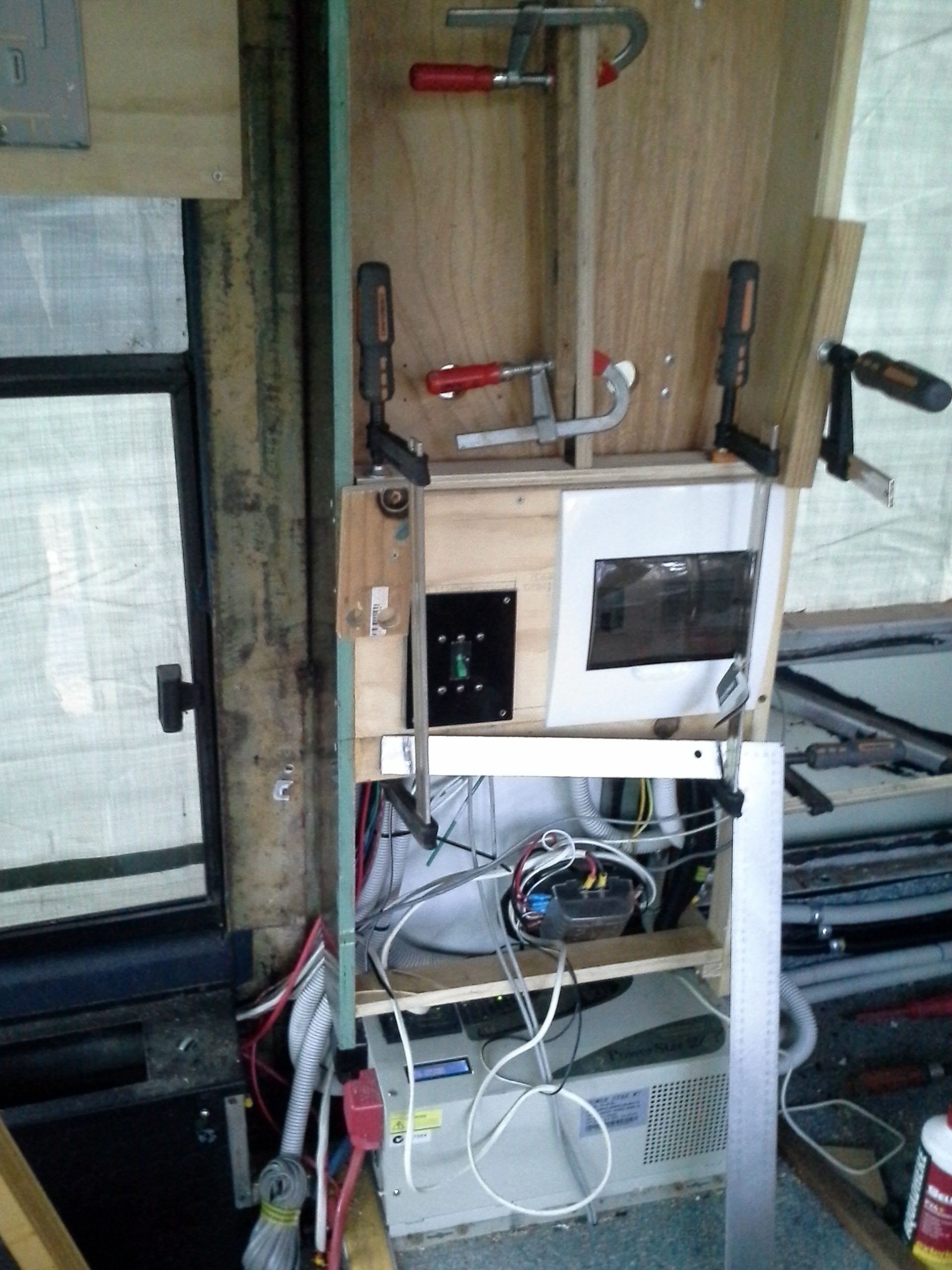
The large white unit below the Cabinet is the 7000w Inverter / Charger.
The recessed center compartment is to house the 2 Solar controllers, the NG rosewood ply is in the process of being applied.
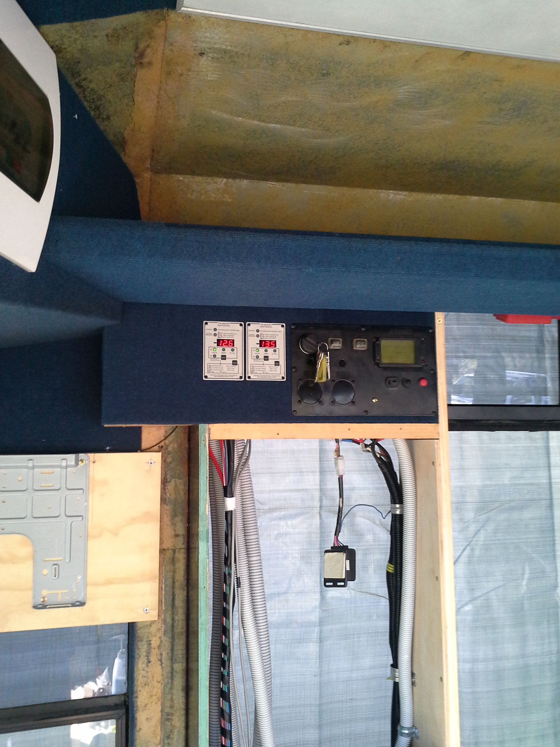
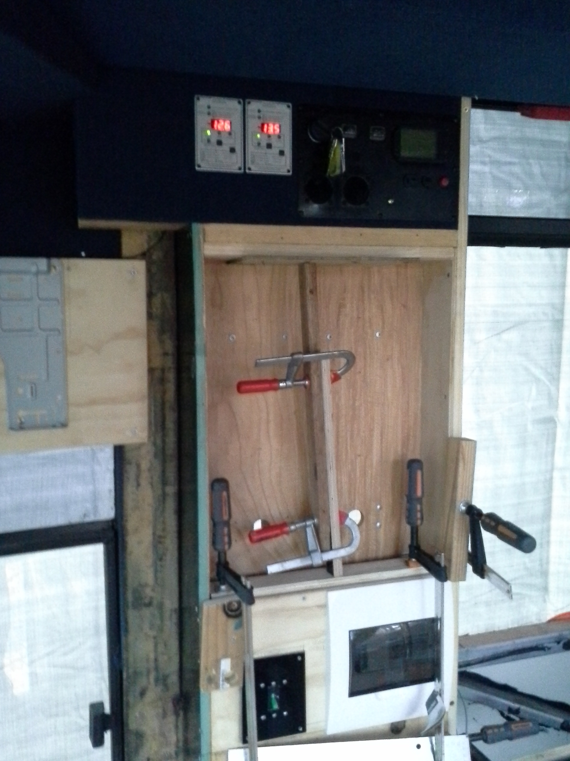
Generator Controls & the Battery monitors in the same panel of the Cabinet, the box hanging from behind the generator controls is for the wireless control of the generator.
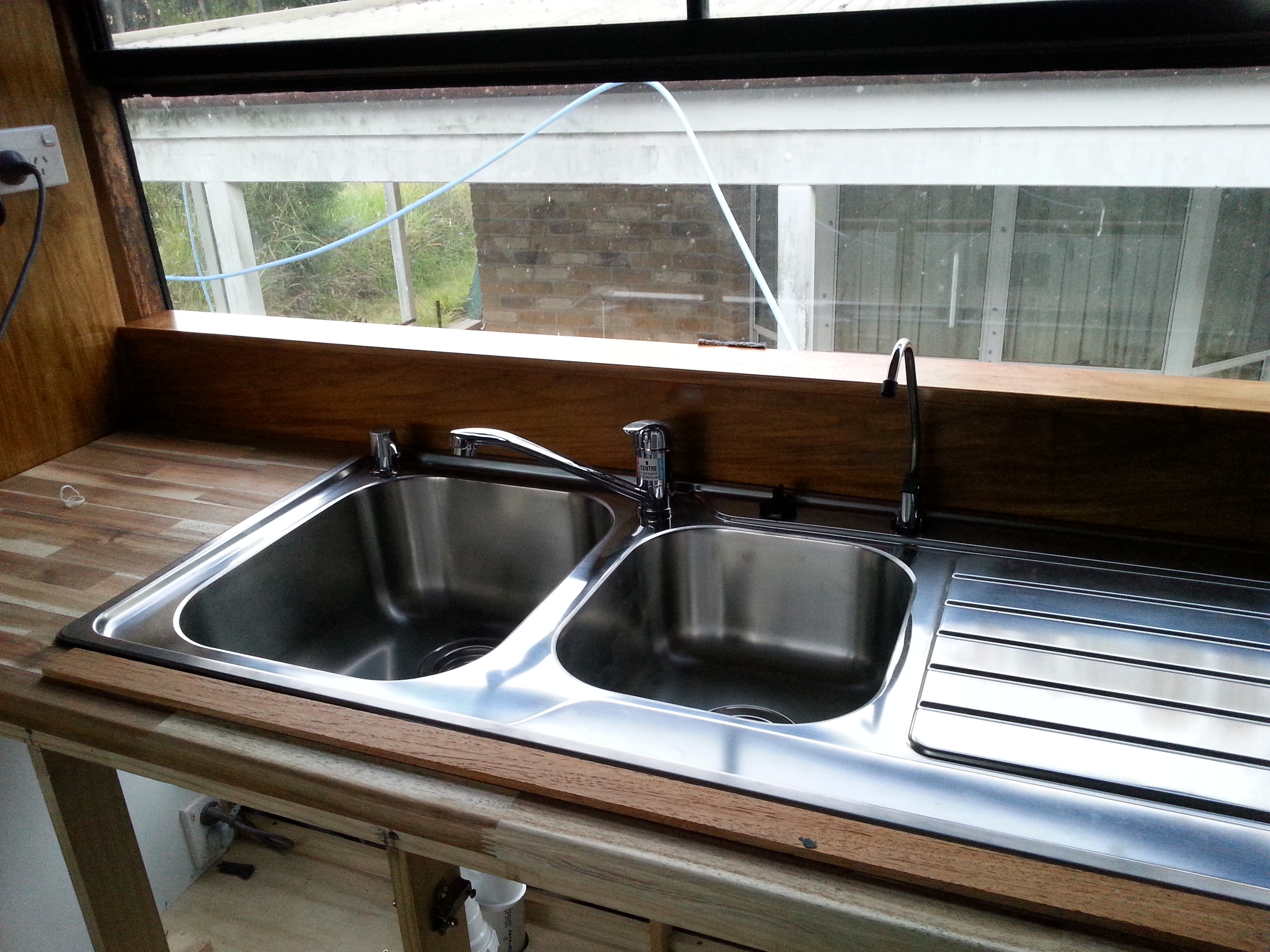
Start of the facings & trims, bench top being fixed to frame.
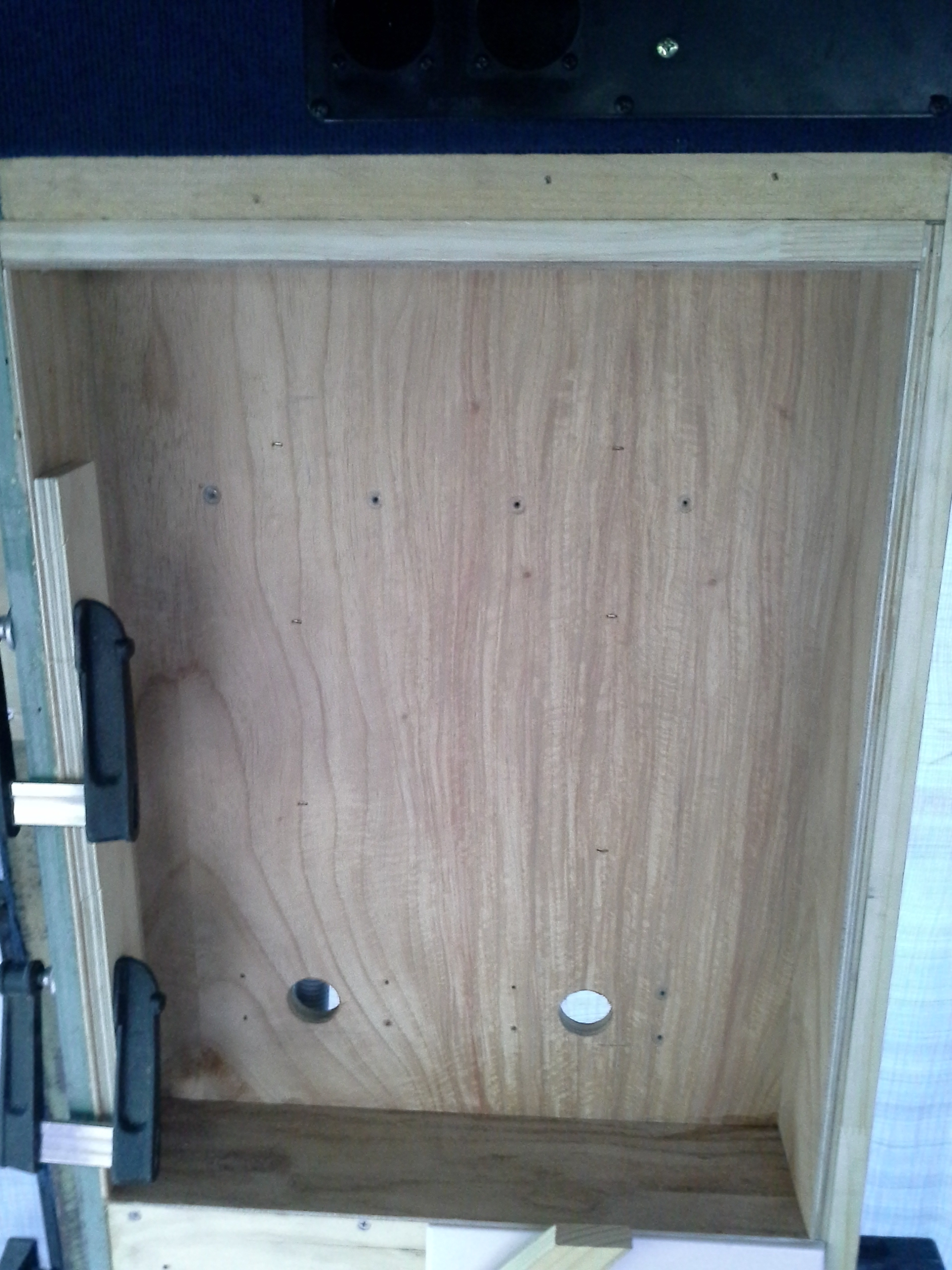
Solar controller enclosure ready for trimming & painting.
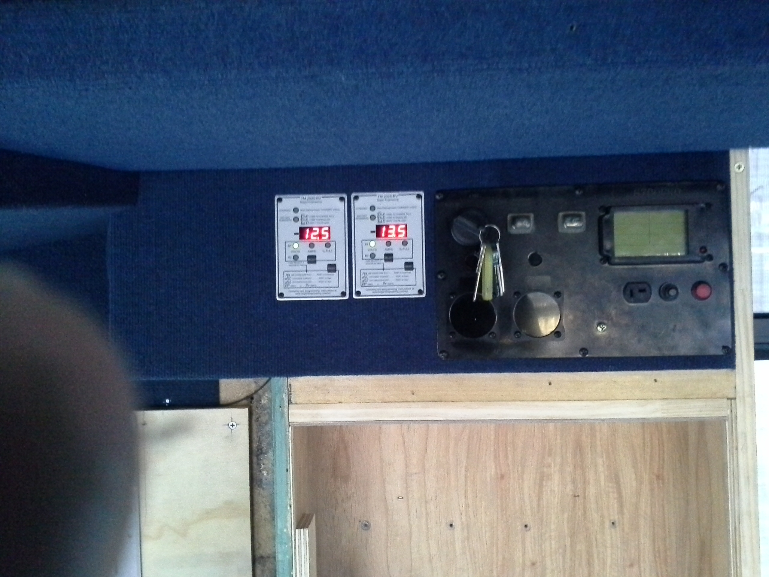
Generator controls & Battery monitors are now operational, the front monitor has an issue with the accuracy of the reading. Will try again to adjust it but may need to replace it.

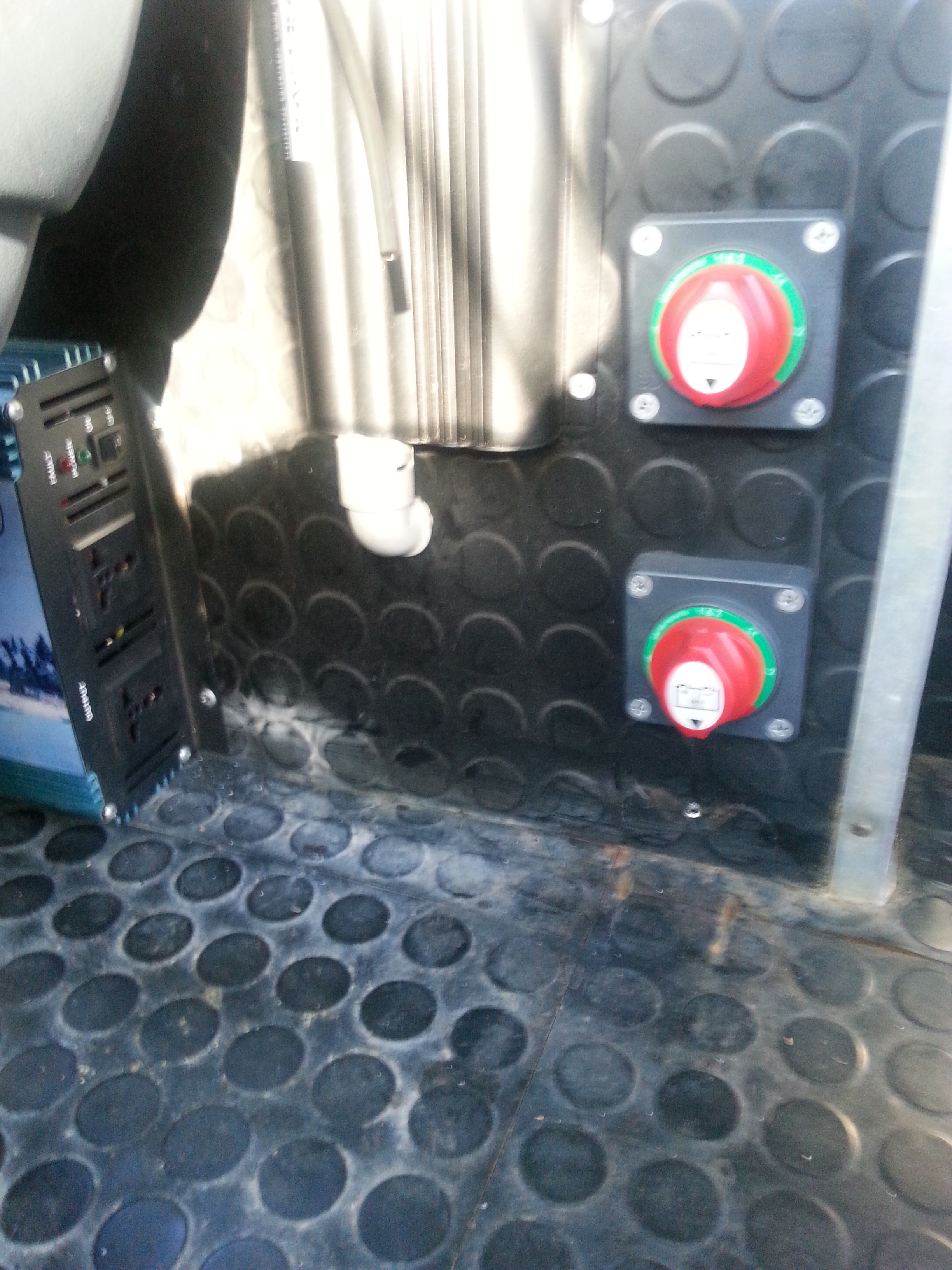
Both Circuit breaker safety switches are in the same panel on the Cabinet.

The Black switch panel to the left of the white switch box is a fault safety switch for the twin 80amp Solar controllers, A requirement when linking 2 Solar controllers to 1 charging circuit?

Upper cabinet finished just waiting for the Solar fault breaker & the AC source switch box to have the facia fitted.
A coat of paint make all things look good.
The sides for the 1st aid enclosure will be covered in the same blue front runner/carpet as the ceiling of the bus.