
All the 240 v cabling has been run. The external infeed socket has been fitted and wired to the switchboard. The New recessed switchboard has been mounted in the enclosed bin over the drivers position and all circuits connected to it. The main in-feed power runs from the socket to a 16 amp RCD circuit breaker then to the 7000 w inverter-charger and back to a 20 amp RCD circuit breaker in the switchboard.
From here it branches out into four separate circuit breakers – one each for two separate power circuits and one each for two air-conditioning circuits. The one for the hot water comes directly from the external in-feed RCD circuit breaker through 10 amp circuit breaker. This will only allow the use of the 240 v hot water system when connected to external -power or generator.

The Generator is to be mounted in its own sound proof enclosure & will be fitted on a slide system to allow ease of servicing.
The system is now connected and charging the Full 1060 A/H house battery bank. The system seems to be working well as during power failures the inverter switches over fast enough to stop the washing machine or Air-Conditioners from losing power & shutting down.
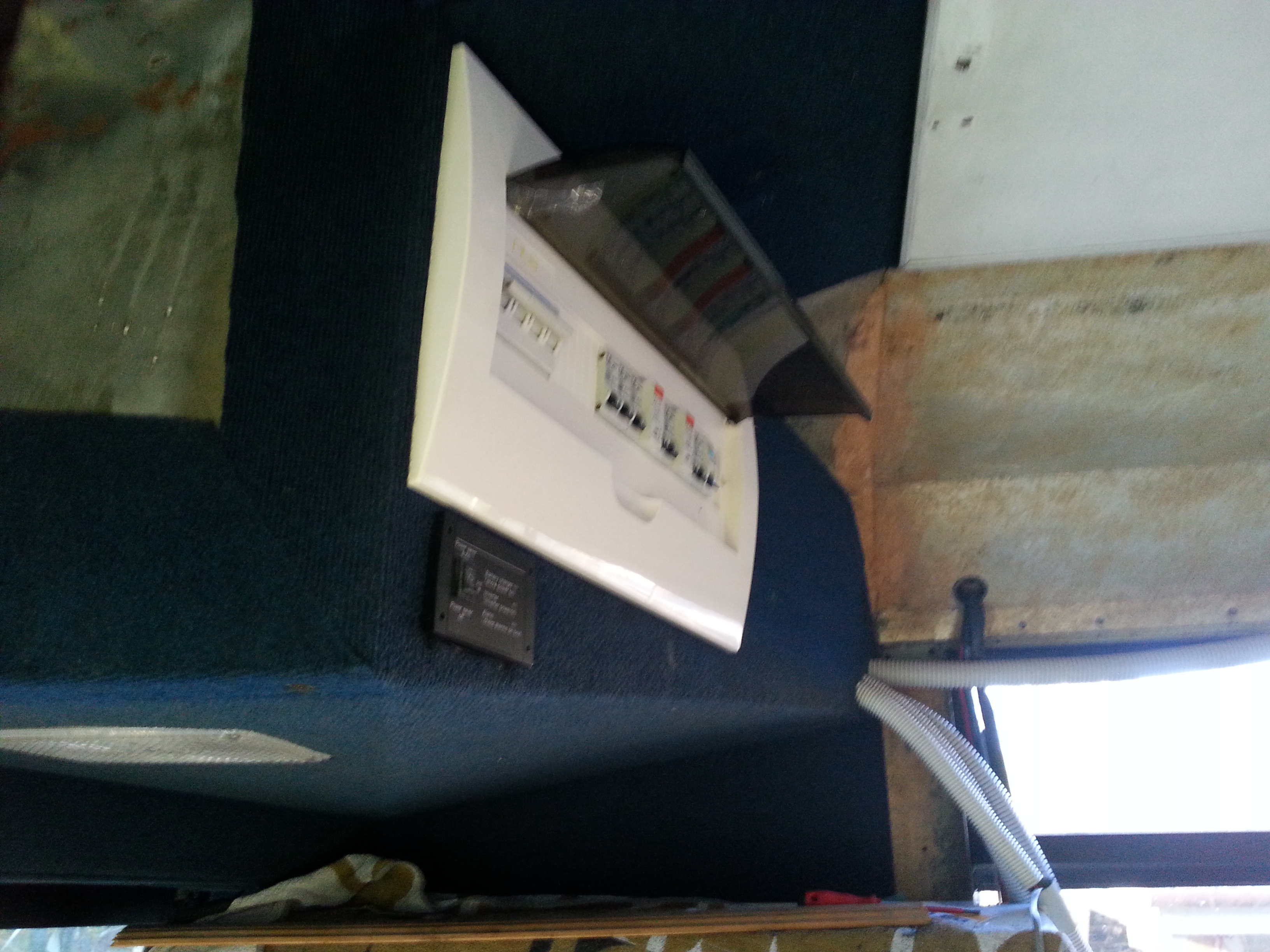
The New Circuit control enclosure is mounted over the driver in the enclosed bin.
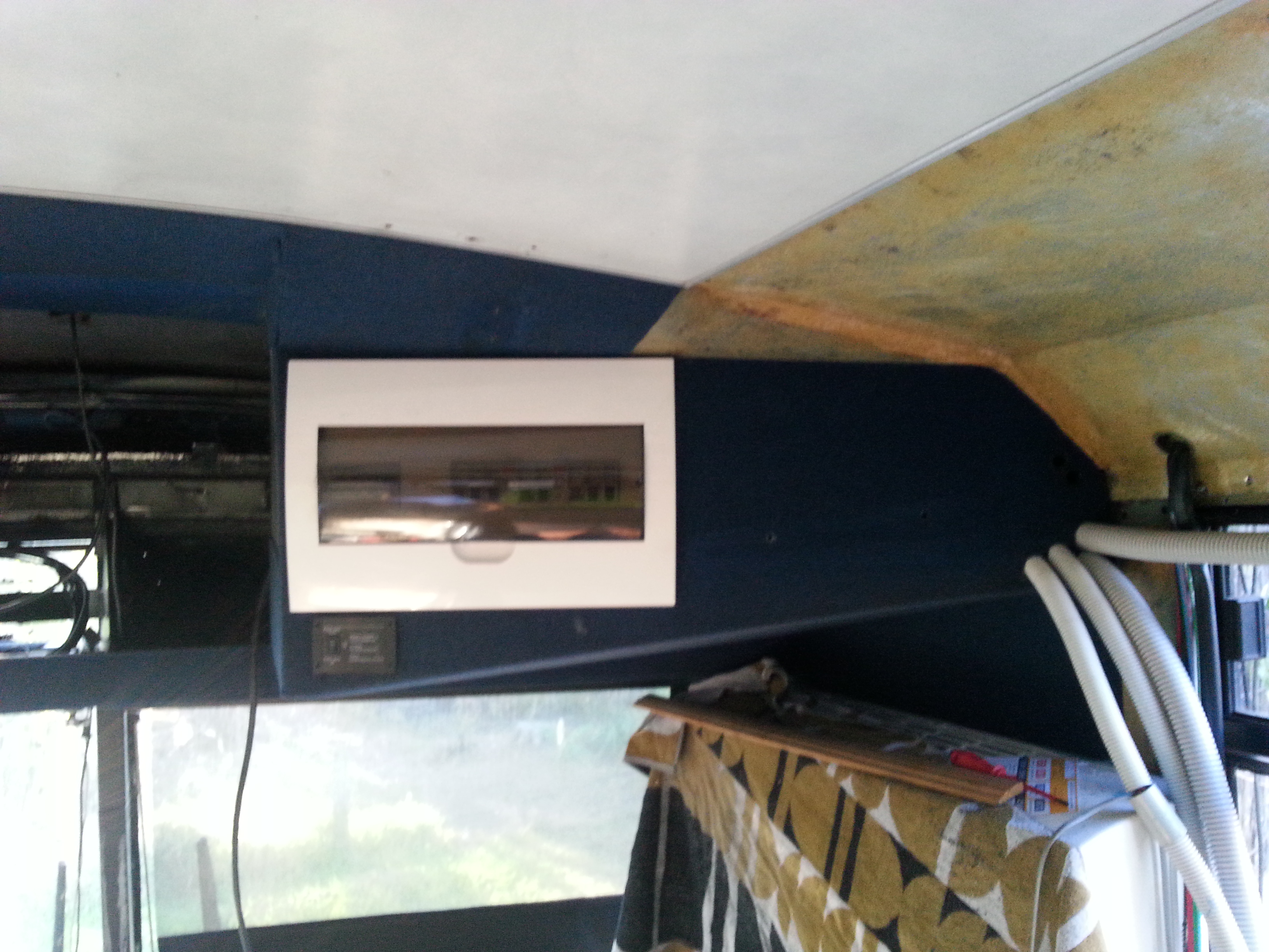
New recessed Breaker control Box

The new mains power curcuit control box, this unit has a change over switch for the front Air Conditioner to allow it to be run from the 24v inverter or Mains Power.

Inverter in charge mode.
